
Deep tunnel defect integrated detection system

A technology for detection systems and tunnels, which is applied in the direction of radio wave measurement systems, measurement devices, and optical test flaws/defects, etc. and other problems, to save on-site working time, fast detection work, and cost savings

Pending Publication Date: 2017-01-04
CHINA MERCHANTS CHONGQING COMM RES & DESIGN INST
View PDF5 Cites 13 Cited by
  • Summary
  • Abstract
  • Description
  • Claims
  • Application Information

AI Technical Summary

Problems solved by technology

[0003] 1) Only one survey line can be detected at a time, and the forward speed is about 3-5km / h, and a detection section usually requires at least 5 survey lines, so the detection rate is relatively low, and the traffic pressure is increasing day by day, fully enclosed This problem will be especially prominent today when tunnel inspection is becoming increasingly difficult
[0004] 2) Facilities on the surface of the tunnel, such as fans and fire-fighting facilities, will affect the forward movement of the radar, making the radar antenna must leave the lining surface, thus affecting the forward speed and detection quality of the radar to a certain extent
[0005] 3) The operation mode of the manual handheld radar antenna is easy to make the staff who lift the instrument feel tired, which will affect the coupling effect between the radar antenna and the tunnel lining surface over time, seriously affecting the detection quality

Method used


Image

  • Deep tunnel defect integrated detection system

Examples


Embodiment Construction

[0017] The preferred embodiments of the present invention will be described in detail below with reference to the accompanying drawings.

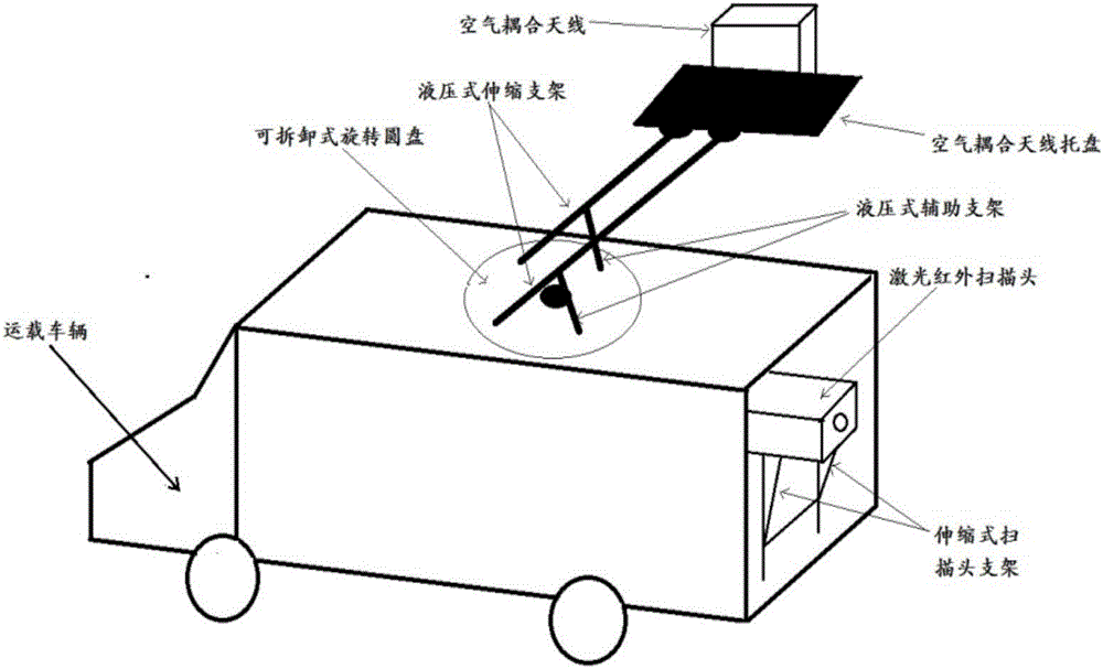
[0018] figure 1 It is a schematic diagram of the structure of the present invention, as shown in the figure, an integrated detection system for deep tunnel defects provided by the present invention, the detection system includes a carrier vehicle, a non-contact three-dimensional laser infrared scanning system installed on the carrier vehicle, Ground radar systems, air-coupled antenna systems for ground radars;

[0019] The non-contact three-dimensional laser infrared scanning system consists of a laser infrared scanning head and a telescopic scanning head bracket. The upper part of the telescopic scanning head bracket, which can telescopically place the laser infrared scanning head from the carrier vehicle to a position at an appropriate distance from the point to be measured;

[0020] The air-coupling antenna system is composed of an air...


PUM


Abstract

The invention relates to a deep tunnel defect integrated detection system and belongs to the technical field of tunnel defect detection. The detection system comprises a transportation vehicle, a non-contact type three-dimensional laser infrared scanning system mounted on the transportation vehicle, a geological radar system and an air coupling antenna system used for a geological radar, wherein the three-dimensional laser infrared scanning system comprises a laser infrared scanning head and a telescopic scanning head support, and by means of the support, the laser infrared scanning head can be telescoped on the transportation vehicle and placed in the position away from a to-be-detected point with proper distance; the air coupling antenna system comprises an air coupling antenna and a telescopic type / foldable type support, the air coupling antenna is fixed above the telescopic type / foldable type support during use, the telescopic type / foldable type support extends from the top of a carriage and extends to the position away from a tunnel lining with the proper distance. With the adoption of the detection system, the field detection work can be more rapid and more accurate, the field work time is saved, the safety risk of the tunnel traffic organization is reduced, the cost is saved, and the detection quality is improved.

Description

technical field [0001] The invention belongs to the technical field of tunnel disease detection and relates to an integrated detection system for deep tunnel diseases. Background technique [0002] At present, in the tunnel inspection industry, the main method for detecting deep defects such as lining thickness and back voids is to use ground-coupled geological radar. However, the working characteristic of today’s geological radar is that it must use manual hand-held radar antennas to slide closely against the surface of the tunnel lining. This work The characteristics make the ground radar detection work mainly have the following three problems: [0003] 1) Only one survey line can be detected at a time, and the forward speed is about 3-5km / h, and a detection section usually requires at least 5 survey lines, so the detection rate is relatively low, and the traffic pressure is increasing day by day, fully enclosed This problem will be particularly prominent today when tunne...

Claims


Application Information

Patent Timeline
IPC IPC(8): G01N21/88G01S13/88
CPCG01N21/8851G01S13/885
Inventor 丁浩刘秋卓吴梦军刘永华李科叶建虎马非曹更任潘勇韩自强
Owner CHINA MERCHANTS CHONGQING COMM RES & DESIGN INST
Learn More