MIMO radar array design method based on non-uniformed subarray partition

A radar array and design method technology, applied in the field of radar, can solve the problems of unbearable hardware cost and algorithm cost, loss of coherent processing gain, impact on target detection and parameter estimation accuracy, etc., and achieve robust anti-interference ability and good interference suppression ability. , beam forming flexible effect

Inactive Publication Date: 2017-01-04
THE PLA INFORMATION ENG UNIV
View PDF3 Cites 11 Cited by
  • Summary
  • Abstract
  • Description
  • Claims
  • Application Information

AI Technical Summary

Problems solved by technology

However, when MIMO radar obtains waveform diversity gain by transmitting orthogonal waveforms, it also loses coherent processing gain, which affects target detection and parameter estimation accuracy.
In addition, in MIMO radar, both the transmitting array and the receiving array have hundreds to thousands of array elements, which require multiple independent transmitting signals and thousands of digital channels at the receiving end, which is impossible in terms of hardware cost and algorithm cost. bearable

Method used


Image

  • MIMO radar array design method based on non-uniformed subarray partition
  • MIMO radar array design method based on non-uniformed subarray partition
  • MIMO radar array design method based on non-uniformed subarray partition

Examples


Embodiment 1

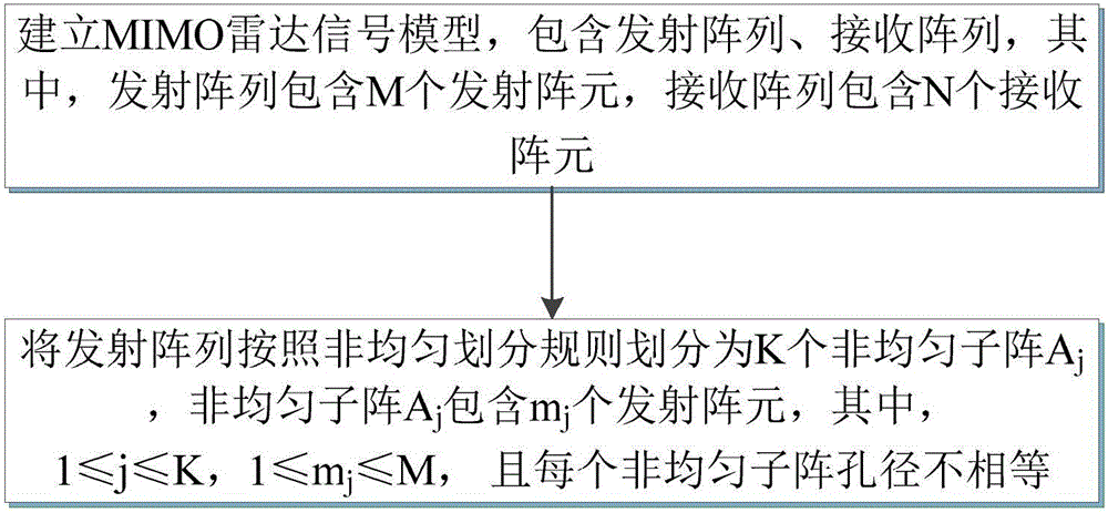
[0030] Example 1, see figure 1 As shown, a MIMO radar array design method based on non-uniform sub-array division includes the following steps:

[0031] Step 1. Establish a MIMO radar signal model, including a transmitting array and a receiving array, where the transmitting array includes M transmitting array elements, and the receiving array includes N receiving array elements;

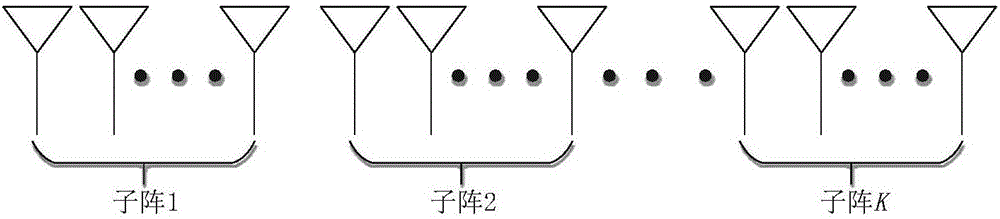
[0032] Step 2: Divide the emission array into K non-uniform sub-arrays A according to the non-uniform division rule j , Non-uniform subarray A j Contains m j A transmitting array element, among them, 1≤j≤K, 1≤m j ≤M, and the aperture of each non-uniform sub-array is not equal.

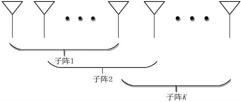
[0033] The present invention divides the transmitting array of the MIMO radar into non-uniform sub-arrays according to certain rules. The aperture of each sub-array is different, and the aperture of the sub-array is getting larger and larger. Different coherent processing gains can be obtained between the sub-arrays. The larger siz...

Embodiment 2

[0034] Example two, see Figure 1~13 As shown, a MIMO radar array design method based on non-uniform sub-array division specifically includes the following content: establish a MIMO radar signal model, including a transmitting array and a receiving array, where the transmitting array includes M transmitting array elements, and the receiving array includes N receiving array elements; divide the transmitting array into K fully overlapping non-uniform sub-arrays according to the full overlap non-uniform division rule, such as Figure 4 As shown, the first element of each fully overlapping non-uniform sub-array is the first element of the emission array, and the number of emission elements contained in the adjacent fully overlapping non-uniform sub-array increases sub-array. The structure matrix is ​​expressed as:

[0035] The output of the k-th subarray is expressed as:

[0036] among them, Represents the array steering vector of the k-th subarray, φ US,k (t) is the emission wavefo...


PUM


Abstract

The invention relates an MIMO radar array design method based on non-uniformed subarray partition. The method comprises the steps of firstly, establishing an MIMO radar signal model which comprises an emission array and a receiving array, wherein the emission array comprises M emission array elements and the receiving array comprises N receiving array elements; then partitioning the emission array into K non-uniformed subarrayAj according to non-uniformed partition rule. The non-uniformed subarrayAj comprises mj emission array elements and each non-uniformed subarray bore diameter is different. According to the method, emission array is partitioned into a plurality of non-uniformed subarraies with different bore diameters through non-uniformed subarray partition to achieve a lower subband level and formed by the minimum variance orthoscopic response beam to achieve a deeper nulling, a higher SINR emission and steadier and stronger antijamming capability.

Description

Technical field [0001] The invention belongs to the field of radar technology, and particularly relates to a MIMO radar array design method based on non-uniform sub-array division. Background technique [0002] Each element of the phased array radar emits coherent signals, which are coherently superimposed in space to form a high-gain transmitting beam. The beam is pointed flexibly. The entire airspace is scanned by controlling the phase shifter. However, when detecting weak targets, It is usually necessary to transmit detection signals with high peak power and high power-aperture gain product, which increases the probability of phased array radar being intercepted, making the radar vulnerable to high-power active interference and anti-radiation missile attacks. In recent years, radar has been widely used in various fields, and MIMO wireless communication theory has also made great developments. Scholars in the radar industry introduced the concept of MIMO into the field of radar...

Claims


Application Information

Patent Timeline
Patent Type & Authority Applications(China)
IPC IPC(8): G01S13/88G06F17/50
CPCG01S13/88G06F30/00
Inventor 郑娜娥顾帅楠任修坤陈松吕品品秦文利李玉翔
Owner THE PLA INFORMATION ENG UNIV
Why Eureka
Try Eureka