A hollow-core photonic crystal fiber coupler

A hollow-core photonic crystal and fiber coupler technology, applied in the field of fiber couplers, can solve problems such as poor stability and mechanical properties, large polarization-related loss, complicated manufacturing process, etc., and achieve small additional loss, large return loss, and reflection. The effect of low loss and polarization dependent loss

Active Publication Date: 2020-02-28
BEIHANG UNIV
View PDF5 Cites 0 Cited by
  • Summary
  • Abstract
  • Description
  • Claims
  • Application Information

AI Technical Summary

Problems solved by technology

The splitting ratio of the photonic crystal fiber coupler made by the grinding method can be adjusted according to the matching angle, but the precision of the grinding depth is difficult to control, the polarization-related loss is large, and the refractive index matching glue will enter the air hole, the manufacturing process is complicated, and the stability and mechanical Poor, mainly used in laboratories
[0005] Since the air hole wall of the hollow-core photonic crystal fiber is thinner, generally less than 200nμ, the above-mentioned process technology of the solid-core photonic crystal fiber coupler is not suitable for the manufacture of the hollow-core photonic crystal fiber coupler. With the GRIN lens (gradient refractive index Lens) manufacturing process and the improvement of axis accuracy, the micro-optical coupler can meet the demand in terms of loss and process

Method used


Image

  • A hollow-core photonic crystal fiber coupler
  • A hollow-core photonic crystal fiber coupler
  • A hollow-core photonic crystal fiber coupler

Examples


Embodiment Construction

[0022] The present invention will be further described in detail below with reference to the drawings and embodiments.

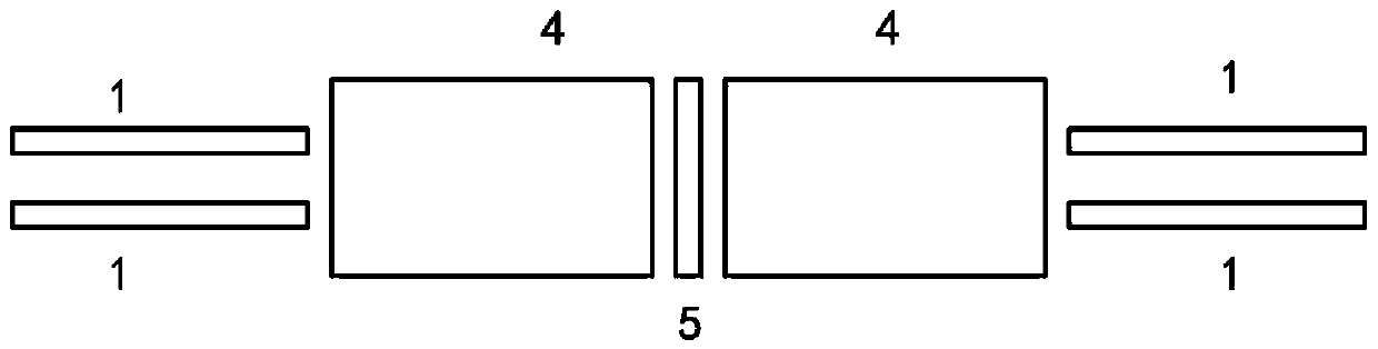
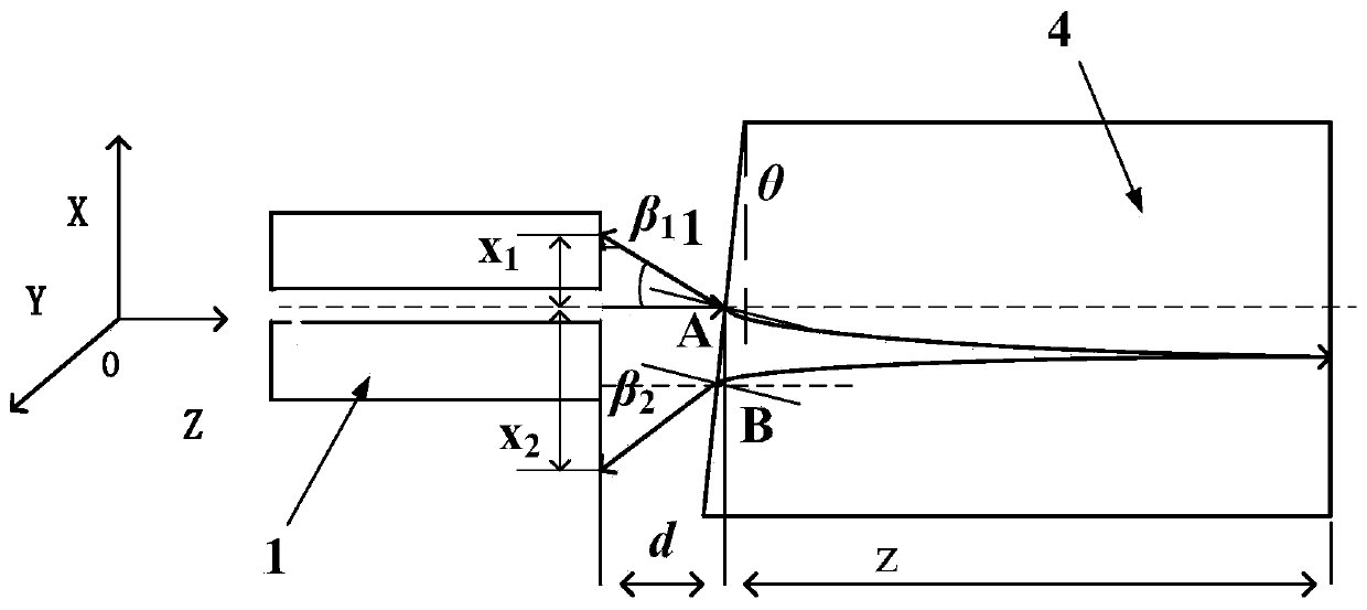
[0023] The invention provides a hollow-core photonic crystal fiber coupler, such as figure 1 As shown, the hollow-core photonic crystal fiber coupler is composed of two dual-fiber collimators and a reflective film 5. The dual-fiber collimator is composed of two hollow-core photonic crystal fibers 1 and a GRIN lens 4. A reflective film 5 with a certain reflectivity is inserted between the two dual-fiber collimators according to the requirements of the splitting ratio. figure 1 The optical path shown is arranged in sequence with the first dual-fiber collimator, the reflective film 5, and the second dual-fiber collimator to form a complete hollow-core photonic crystal fiber coupler. The distance d between the pigtail of the hollow core photonic crystal fiber 1 and the center of the front end face of the GRIN lens 4 is between 0.2 and 0.3 mm, the tilt angle of the G...


PUM

PropertyMeasurementUnit
reflectanceaaaaaaaaaa

Abstract

The invention discloses a hollow-core photonic crystal fiber coupler, and belongs to the technical field of fiber couplers. The hollow-core photonic crystal fiber coupler consists of two double-fiber collimators and a reflective diaphragm, wherein each double-fiber collimator consists of two hollow-core photonic crystal fibers and a GRIN (gradient reflective index) lens, the distance between the tail fiber of each hollow-core photonic crystal fiber and the front end surface of the GRIN lens is 0.2 to 0.3mm, the titling angle of the front end surface of the GRIN lens is 3 degrees, and the mode field radius of each hollow-core photonic crystal fiber is 5mum. The hollow-core photonic crystal fiber coupler has the advantages that the oblique 8-degree grinding and polishing on the end surface of fiber are not needed, and only the cutting is performed, so that the requirement of return loss can be met, and the problem of damage to band gap fiber structure and optical property due to treatment of the end surface of the hollow-core photonic crystal fiber is solved; the additional loss is little, the return loss is large, the film plating is not needed on the end surface of the fiber, and the splitting ratio can be adjusted through changing the transmissivity of the diaphragm.

Description

technical field [0001] The invention belongs to the technical field of optical fiber couplers, and in particular relates to a hollow-core photonic crystal optical fiber coupler. Background technique [0002] Optical fiber coupler is an optical passive device that realizes optical signal splitting and combining, and is an important basic component of optical fiber sensing and optical fiber communication. Compared with ordinary optical fibers, hollow-core photonic crystal fibers have the characteristics of low magnetic sensitivity, strong radiation resistance, and high temperature stability. It can improve the accuracy of optical fiber gyroscopes in space applications. All photonic crystal optical fiber gyroscopes require optical fibers In addition to the hollow-core photonic crystal fiber used in the ring, photonic crystal fiber is also used in other parts of the optical path, so a hollow-core photonic crystal fiber coupler is required. [0003] At present, there are solid-c...

Claims


Application Information

Patent Timeline
Patent Type & Authority Patents(China)
IPC IPC(8): G02B6/32
CPCG02B6/32
Inventor 李彦赵远徐小斌蔡伟金靖宋凝芳
Owner BEIHANG UNIV
Why Eureka
Try Eureka