Image forming apparatus and image forming method
An image and equipment technology, applied in the field of image forming equipment, to achieve the effect of reducing power consumption, reducing power, and simple settings
- Summary
- Abstract
- Description
- Claims
- Application Information
AI Technical Summary
Problems solved by technology
Method used
Image
Examples
Embodiment approach 1
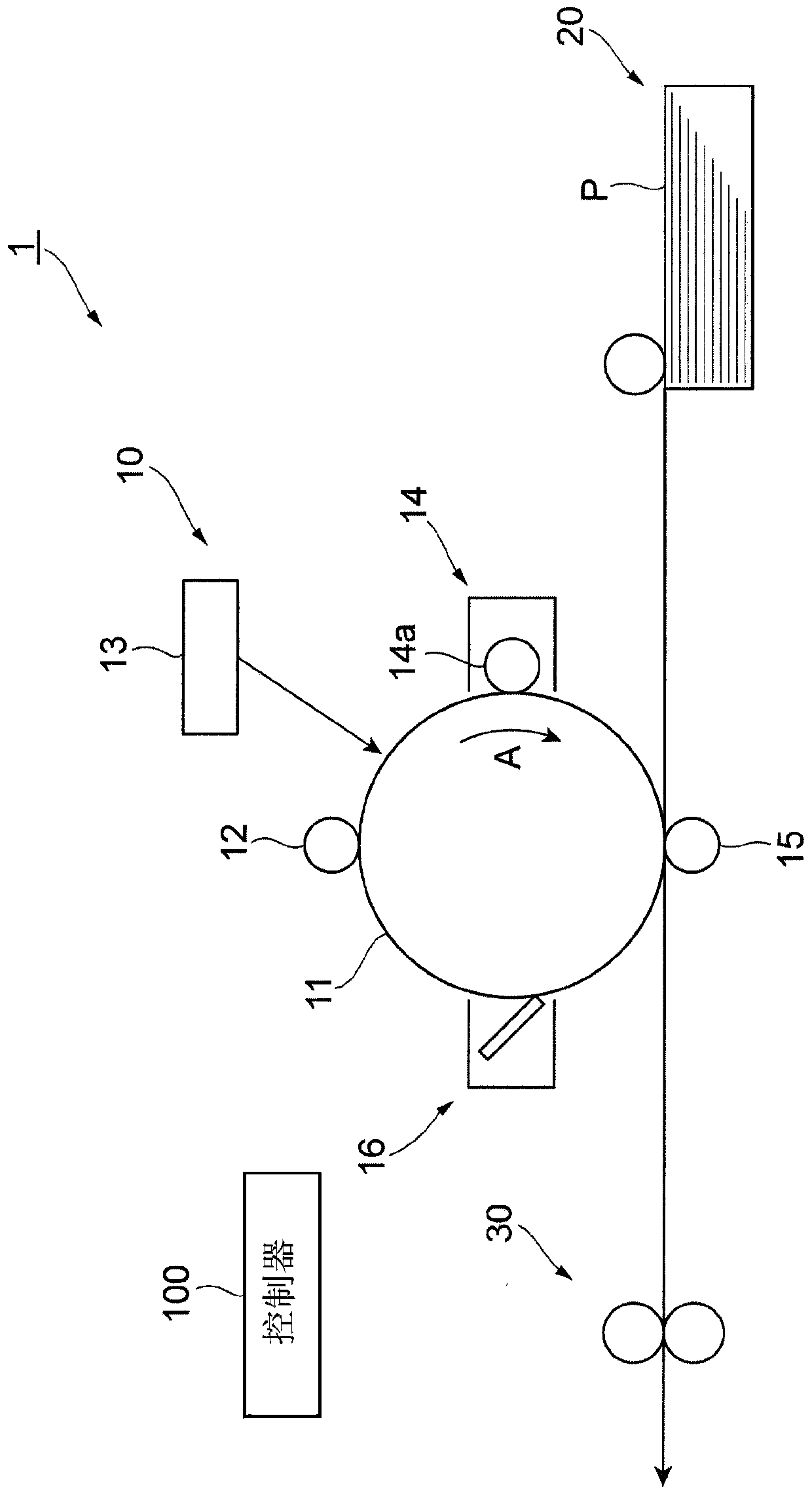
[0048] figure 1 The overall configuration of the image forming apparatus 1 according to the exemplary embodiment is illustrated.
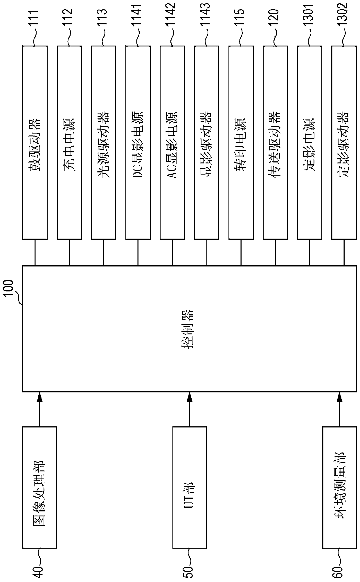
[0049] The image forming apparatus 1 includes: an image forming section 10 , a paper supply section 20 , a fixing section 30 , and a controller 100 . The image forming section 10 forms a monochrome (for example, black) toner image via an electrophotographic system. The paper supply unit 20 supplies paper P toward the image forming unit 10 . The fixing unit 30 fixes the image (toner image) formed on the paper P by the image forming unit 10 . The controller 100 controls operations of various parts of the image forming apparatus 1 .
[0050] The image forming section 10 has figure 1 The photosensitive drum 11 is rotatable in the direction indicated by the arrow A in it. The image forming section 10 also has a charging roller 12 , an exposure device 13 , a developing device 14 , a transfer roller 15 , and a cleaning device 16 disposed around the p...
Embodiment approach 2
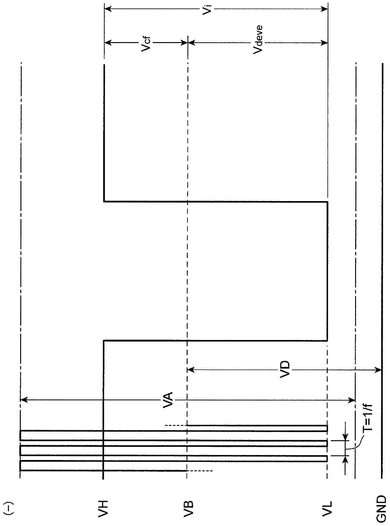
[0107] In Exemplary Embodiment 1, a configuration is employed in which, as the power saving AC developing bias VAr used in the power saving mode, the supply of the AC reference value VA0 in the reference output period Z0 and the supply of the AC reference value VAr in the special output period Z1 are alternately performed. AC special value VA1. In other words, in Exemplary Embodiment 1, the power-saving AC developing bias Var has two values (AC reference value VA0 and AC special value VA1 ). In contrast, in Exemplary Embodiment 2, the power saving AC developing bias VAr is multi-valued. In Exemplary Embodiment 2, components or features similar to those in Exemplary Embodiment 1 are denoted by the same symbols, and detailed descriptions of these components or features are omitted.
[0108] The development mode according to Exemplary Embodiment 2 will be described in more detail below.
[0109] Figure 9A An example of the waveform of the normal AC developing bias VAs used ...
Embodiment approach 3
[0119] In Exemplary Embodiments 1 and 2, designation of the normal mode or the power saving mode is received from the user, and the AC developing bias VA to be supplied is changed between the normal mode and the power saving mode. In contrast, in Exemplary Embodiment 3, the kind of AC developing bias VA to be supplied is set according to the type of image formed on the photosensitive drum 11 . In Exemplary Embodiment 3, components or features similar to those in Exemplary Embodiments 1 and 2 are denoted by the same symbols, and detailed descriptions of these components or features are omitted.
[0120] Figure 10 is a flowchart illustrating steps for setting the developing conditions in the image forming operation according to Exemplary Embodiment 3.
[0121] In this process, first, the controller 100 acquires image data input from the image processing section 40, and analyzes the acquired image data (step 110). In step 110, the controller 100 analyzes the acquired image dat...
PUM
 Abstract
Description
Claims
Application Information
 - R&D
- Intellectual Property
- Life Sciences
- Materials
- Tech Scout
- Unparalleled Data Quality
- Higher Quality Content
- 60% Fewer Hallucinations
Browse by: Latest US Patents, China's latest patents, Technical Efficacy Thesaurus, Application Domain, Technology Topic, Popular Technical Reports.
© 2025 PatSnap. All rights reserved.Legal|Privacy policy|Modern Slavery Act Transparency Statement|Sitemap|About US| Contact US: help@patsnap.com


