Supercharge Your Innovation With Domain-Expert AI Agents!

A simulation layout method of heater in electrical function box

A layout method and internal heater technology, applied in design optimization/simulation, instrumentation, electrical digital data processing, etc., can solve the problem of secondary circuit insulation level drop, high humidity, terminal block screws, and connecting sheet relay core rusting And other issues

Active Publication Date: 2019-05-31
ELECTRIC POWER RESEARCH INSTITUTE, CHINA SOUTHERN POWER GRID CO LTD
View PDF2 Cites 0 Cited by
  • Summary
  • Abstract
  • Description
  • Claims
  • Application Information

AI Technical Summary

Problems solved by technology

[0002] Electrical functional boxes such as HSBC cabinets, terminal boxes, switchgear mechanism boxes, and power boxes are intermediate links between electrical equipment and measurement and control equipment, protection equipment, and communication equipment. When the environment in the electrical functional box does not meet the requirements, the electrical functional box Condensation is easy to occur inside, which will cause the insulation level of the secondary circuit installed in the electrical function box to drop, and even cause malfunction or refusal to operate in serious cases, causing accidents
In addition, it will also rust the terminal block screws, connecting pieces and relay core, resulting in poor contact and shortening the life of the secondary components in the secondary circuit
[0003] The inventor of the present application found that the main reason for the above problems in actual work is that the distribution of the heaters installed in the electrical function box is unreasonable, resulting in high humidity in some areas in the electrical function box, resulting in condensation in the electrical function box. Exposure phenomenon, reducing the reliability of equipment operation in the electrical function box

Method used


Image

  • A simulation layout method of heater in electrical function box
  • A simulation layout method of heater in electrical function box
  • A simulation layout method of heater in electrical function box

Examples


Embodiment Construction

[0029] For ease of understanding, the simulated layout method of the heater in the electrical function box provided by the embodiment of the present invention will be described in detail below in conjunction with the accompanying drawings.

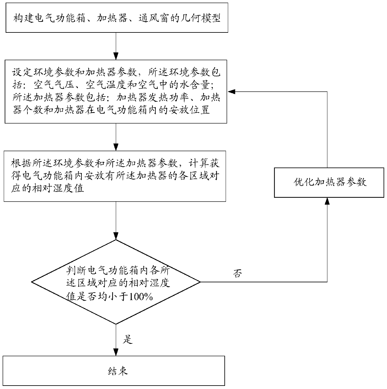
[0030] see figure 1 , the simulation layout method of the heater in the electrical function box provided by the embodiment of the present invention includes:

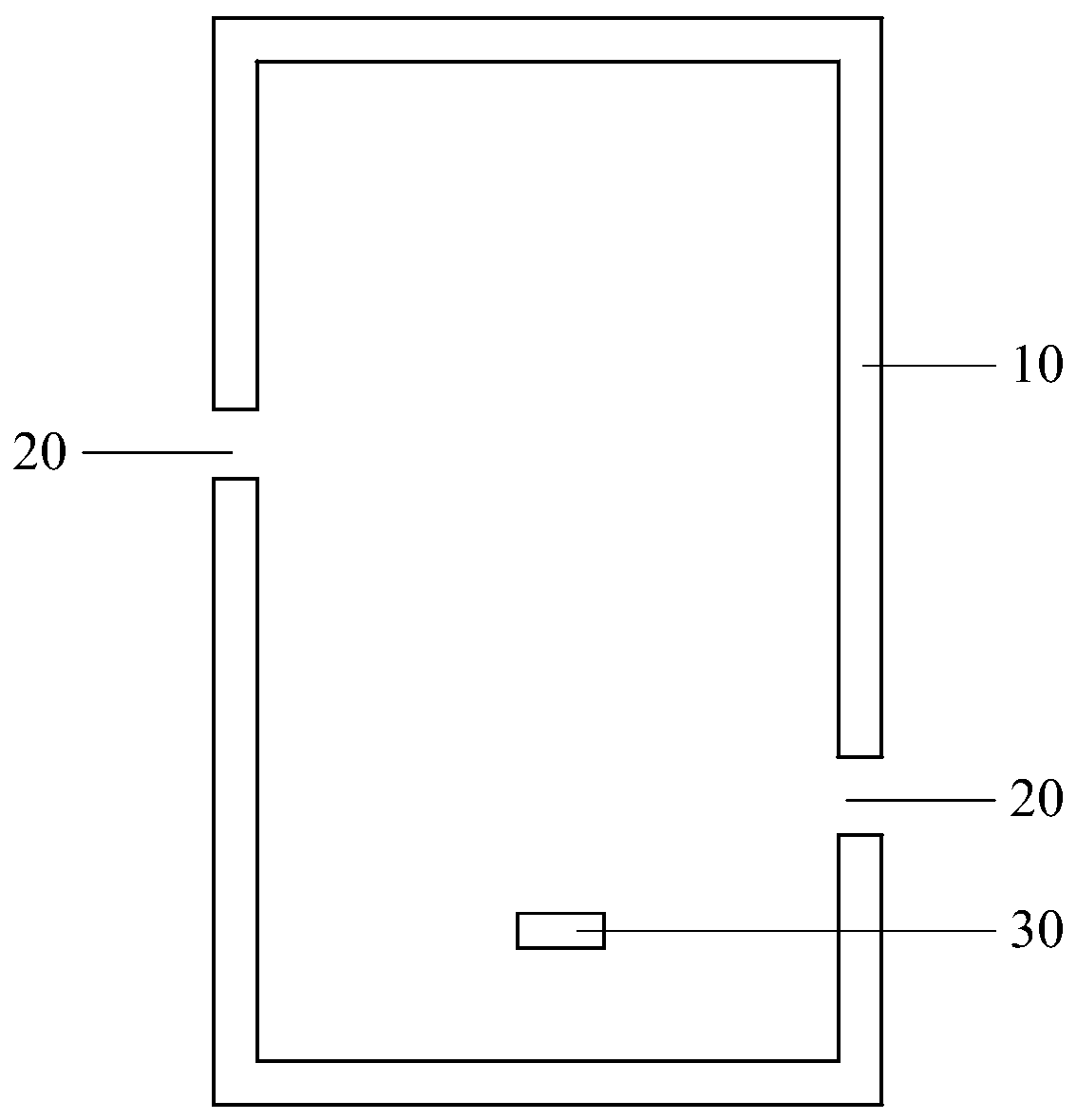
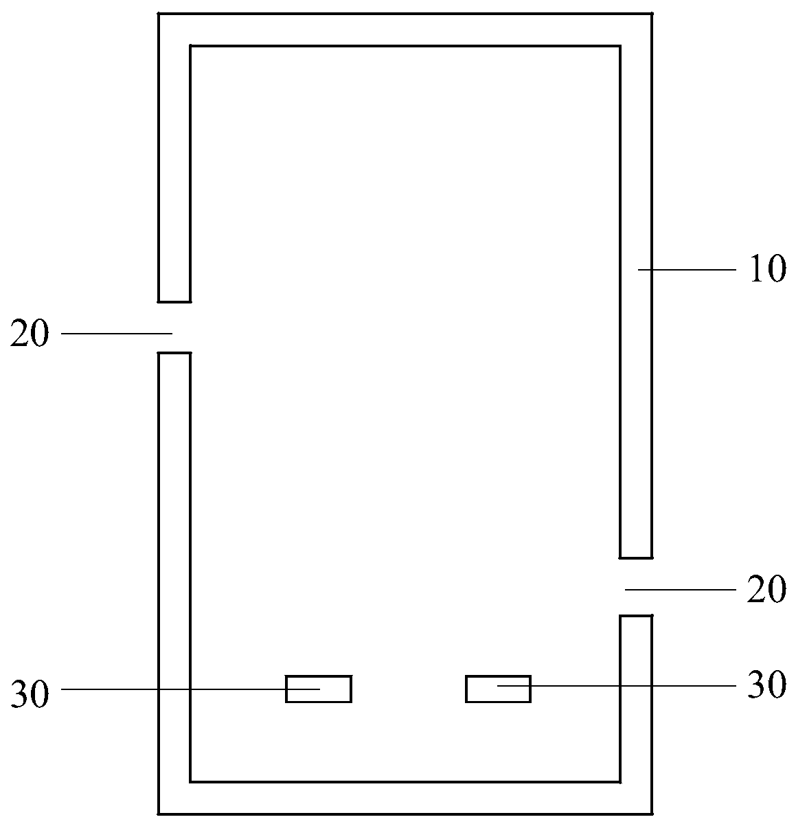
[0031] Step 1. Construct the geometric model of the electrical function box, heater, and ventilation window; construct the geometric model of the electrical function box, heater, and ventilation window, including: the size and material of the electrical function box, the size and material of the heater, and the electrical The size of the ventilation window on the function box and the opening position of the ventilation window on the electrical function box.

[0032] Step 2, setting environmental parameters and heater parameters, the environmental parameters include: air pressure, a...


PUM


Abstract

The invention discloses a simulation arrangement method of heaters in an electrical function box, relates to the technical field of electrical control, and aims to solve the problem that the reliability of running of equipment in the electrical function box is low due to the condensation phenomenon in the electrical function box. The simulation arrangement method of the heaters in the electrical function box comprises steps as follows: establishing geometric models of the electrical function box, heaters and ventilation windows; setting environment parameters and heater parameters; calculating and acquiring a relative humidity value corresponding to each area in the electrical function box according to the environment parameters and the heater parameters; judging whether the relative humidity value corresponding to each area in the electrical function box is smaller than 100%, and when the relative humidity value corresponding to at least one area in the electrical function box reaches 100%, optimizing the heater parameters until the relative humidity value corresponding to each area in the electrical function box is smaller than 100%. The provided simulation arrangement method of the heaters in the electrical function box is used for optimizing the heater parameters.

Description

technical field [0001] The invention relates to the technical field of electrical control, in particular to a simulation arrangement method for heaters in an electrical function box. Background technique [0002] Electrical functional boxes such as HSBC cabinets, terminal boxes, switchgear mechanism boxes, and power boxes are intermediate links between electrical equipment and measurement and control equipment, protection equipment, and communication equipment. When the environment in the electrical functional box does not meet the requirements, the electrical functional box Condensation is easy to occur inside, which in turn leads to a decrease in the insulation level of the secondary circuit installed in the electrical function box, and even causes malfunction or refusal to operate in severe cases, causing accidents. In addition, it will also rust the terminal block screws, connecting pieces and relay core, resulting in poor contact and shortening the life of the secondary...

Claims


Application Information

Patent Timeline
Patent Type & Authority Patents(China)
IPC IPC(8): G06F17/50
CPCG06F30/20
Inventor 袁耀王颂邹林杨家辉程建伟彭在兴李锐海
Owner ELECTRIC POWER RESEARCH INSTITUTE, CHINA SOUTHERN POWER GRID CO LTD
Features
  • R&D
  • Intellectual Property
  • Life Sciences
  • Materials
  • Tech Scout
  • Unparalleled Data Quality
  • Higher Quality Content
  • 60% Fewer Hallucinations
Learn More