
Split mounting type battery box module fixing frame and power battery box provided with same

A battery module and battery box technology, which is applied to battery pack parts, circuits, electrical components, etc., can solve the problems of battery box bottom wall falling off, complex production process, unfavorable disassembly and assembly, etc., and achieve high assembly efficiency and structural strength High, simple structure effect

Pending Publication Date: 2017-01-04
江苏和中普方新能源科技有限公司
View PDF8 Cites 15 Cited by
  • Summary
  • Abstract
  • Description
  • Claims
  • Application Information

AI Technical Summary

Problems solved by technology

[0003] At present, the battery box has a fixing frame for fixing the battery module, the management system or other original components. Most of the fixing frames are fixed on the bottom wall of the box by welding, but the traditional fixing frame structure is easy to Affected by external forces such as bumps, it will fall off the bottom wall of the battery box. In addition, the traditional fixing frame is welded to each other through beams, vertical beams and other beams. The production process is relatively complicated, which is not conducive to disassembly and assembly.

Method used


Image

  • Split mounting type battery box module fixing frame and power battery box provided with same
  • Split mounting type battery box module fixing frame and power battery box provided with same
  • Split mounting type battery box module fixing frame and power battery box provided with same

Examples


Embodiment

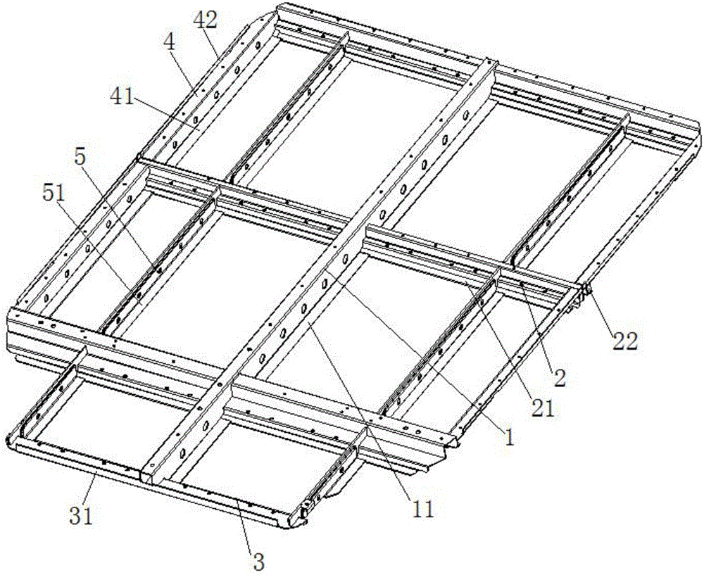
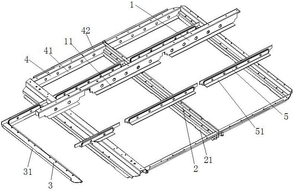
[0036] Example: such as figure 1 and 2 As shown, the assembled battery box module fixing frame of this embodiment includes a longitudinal beam keel 1, a plurality of cross beam keels 2 and a plurality of side beams 4;

[0037] A plurality of the above-mentioned beam keels 2 are arranged at intervals and parallel to each other, the above-mentioned longitudinal beam keels 1 are vertically arranged in the middle position of the plurality of the above-mentioned beam keels 2, and are respectively engaged on the multiple above-mentioned beam keels 2;

[0038] The ends of two adjacent beam keels 2 are connected by side beams 4;

[0039] Both sides of the bottom of the beam keel 2 are horizontally provided with a first side plate 21, the bottom of both sides of the above-mentioned longitudinal beam keel 1 is horizontally provided with a second side plate 11, and the bottom of the above-mentioned side beam 4 is horizontally provided with a third side plate 41. Limiting gaps are provi...


PUM


Abstract

The invention relates to a split mounting type battery box module fixing frame. The split mounting type battery box module fixing frame comprises a longitudinal beam keel, multiple cross beam keels and multiple boundary beams, wherein the multiple cross beam keels are arranged at intervals in parallel, and the longitudinal beam keel is perpendicularly arranged in the middle of the multiple cross beam keels and clamped on the multiple cross beam keels; the ends of every two adjacent cross beam keels are connected through the boundary beams, first side plates are horizontally arranged on the two sides of the bottom of each cross beam keel respectively, second side plates are horizontally arranged on the two sides of the bottom of the longitudinal beam keel respectively, and a third side plate is horizontally arranged on the bottom of each boundary beam; limiting notches are formed in the first side plates corresponding to the second side plates and the third side plates, and the two ends of each second side plate and the two ends of each third side plate stretch into the corresponding limiting notches respectively and abut against the corresponding first side plates; the first side plates, the second side plates and the third side plates are all fixed to the bottom wall of an electric box, and fold fins used for being connected with the side wall of the electric box are arranged at the two ends of each cross beam keel respectively. The split mounting type battery box module fixing frame has the advantages that the whole module fixing frame is convenient to assemble and disassemble, high in structural strength and high in stability.

Description

technical field [0001] The invention relates to the technical field of power battery boxes, in particular to an assembled battery box module fixing frame and a power battery box with the same. Background technique [0002] At present, the global automobile industry is facing the huge challenge of energy and environmental issues; pure electric vehicles with high energy utilization rate and no pollution to the environment are increasingly becoming the development direction of the future automobile industry. As the core component of pure electric vehicles, the safety of the power battery pack will directly affect the performance of the whole vehicle. The battery system of an electric vehicle consists of battery pack box, power battery module, module connection part and battery management system. The structural strength of the battery pack directly affects the safety of the entire battery system and the safety of electric vehicles. sex. [0003] At present, the battery box has...

Claims


Application Information

Patent Timeline
IPC IPC(8): H01M2/10H01M50/20
CPCH01M50/20Y02E60/10
Inventor 王小龙刘治秋李鑫刘刚盛力杨槐
Owner 江苏和中普方新能源科技有限公司
Learn More