High gain microstrip antenna based on air gap
A technology of microstrip antenna and air gap, which is applied in the direction of antenna coupling, antenna grounding device, antenna grounding switch structure connection, etc., can solve the problems of microstrip antenna, such as large volume, high cost, and low radiation efficiency, and achieve easy array formation, Good directivity and high radiation efficiency
- Summary
- Abstract
- Description
- Claims
- Application Information
AI Technical Summary
Problems solved by technology
Method used
Image
Examples
Embodiment 1
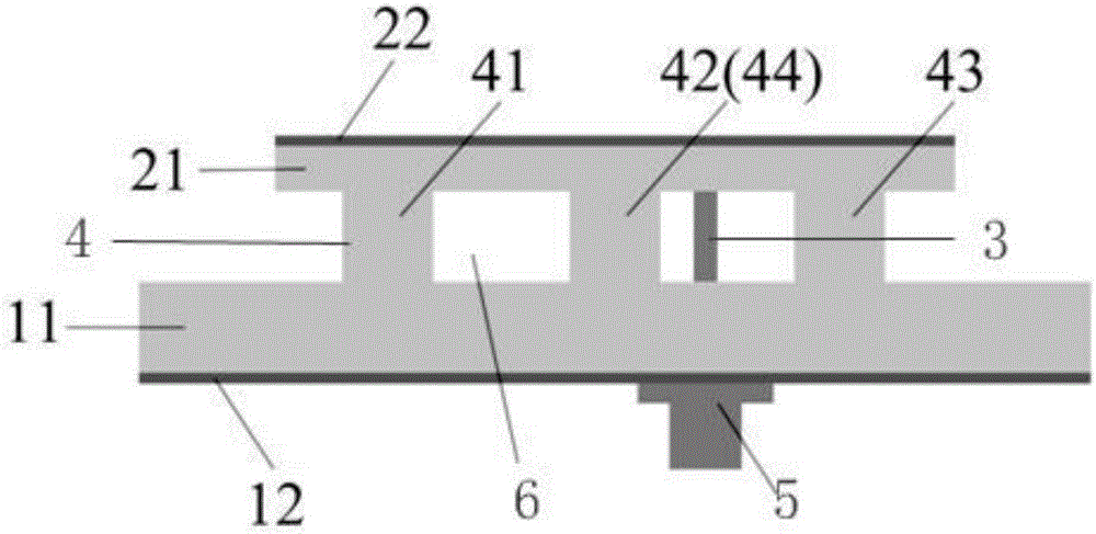
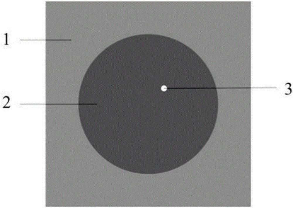
[0030] Such as figure 1 , 2 As shown, the high-gain microstrip antenna based on the air gap 6 includes a floor 1, a radiating plate 2, a pillar 4 and a coaxially fed SMA head 5, wherein the floor 1 and the radiating plate 2 are arranged in parallel, and the distance between the floor 1 and the radiating plate 2 is There is a gap as an air gap 6 between them, and the floor 1 is connected to the radiation board 2 through the pillar 4; the probe 3 of the coaxially fed SMA head passes through the floor 1 and connects to the radiation board 2.
[0031] Wherein, the transverse section of the floor 1 is square, its length is 18.5 mm, its width is 18.5 mm, and the thickness of the floor 1 is 0.8 mm; the transverse section of the radiation plate 2 is circular, its radius is 5.9 mm, and Plate 2 has a thickness of 0.25 mm. The center of the floor 1 is aligned with the center of the radiation plate 2; the microstrip receiving antenna includes four pillars 4, such as figure 1 As shown, ...
Embodiment 2
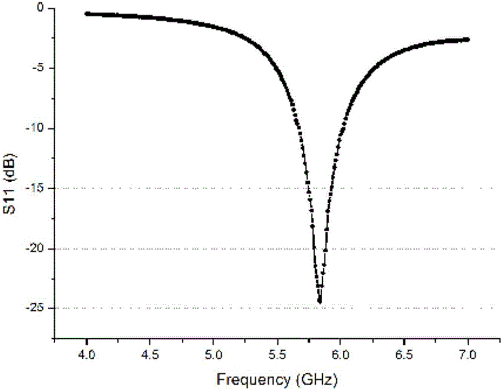
[0036] This embodiment has carried out concrete experiment to the microstrip antenna that embodiment 1 provides, and its experimental result is as follows image 3 , 4 , 5 shown.
[0037] Such as image 3 As shown, the microstrip antenna provided by Embodiment 1 has an optimal reflection coefficient S near the resonant frequency 5.8GHz 11 =-24.5dB.
[0038] Such as Figure 4 As shown, the gain of the microstrip antenna provided by Embodiment 1 near the resonant frequency of 5.8 GHz is Gain=8.4 dB. The frequency band from 5.6GHz to 5.9GHz is the common ISM frequency band of MPT technology. In this frequency band, the gain of the microstrip antenna is about 7.8dB to 8.4dB.
[0039] Such as Figure 5 as shown, Figure 5 It is the radiation efficiency curve of the microstrip antenna in different frequency bands. The frequency band from 5.6 GHz to 5.9 GHz is a common frequency band for MPT technology. In this frequency band, the radiation efficiency of the microstrip antenn...
PUM
 Abstract
Description
Claims
Application Information
 - R&D
- Intellectual Property
- Life Sciences
- Materials
- Tech Scout
- Unparalleled Data Quality
- Higher Quality Content
- 60% Fewer Hallucinations
Browse by: Latest US Patents, China's latest patents, Technical Efficacy Thesaurus, Application Domain, Technology Topic, Popular Technical Reports.
© 2025 PatSnap. All rights reserved.Legal|Privacy policy|Modern Slavery Act Transparency Statement|Sitemap|About US| Contact US: help@patsnap.com


