

Antenna and wireless router
An antenna and radiator technology, applied in the direction of antenna, antenna coupling, antenna components, etc., can solve the problems of narrow radiator bandwidth, large antenna size, low radiation efficiency, etc. low effect
- Summary
- Abstract
- Description
- Claims
- Application Information
AI Technical Summary
Problems solved by technology
Method used
Image

Examples
Embodiment 1
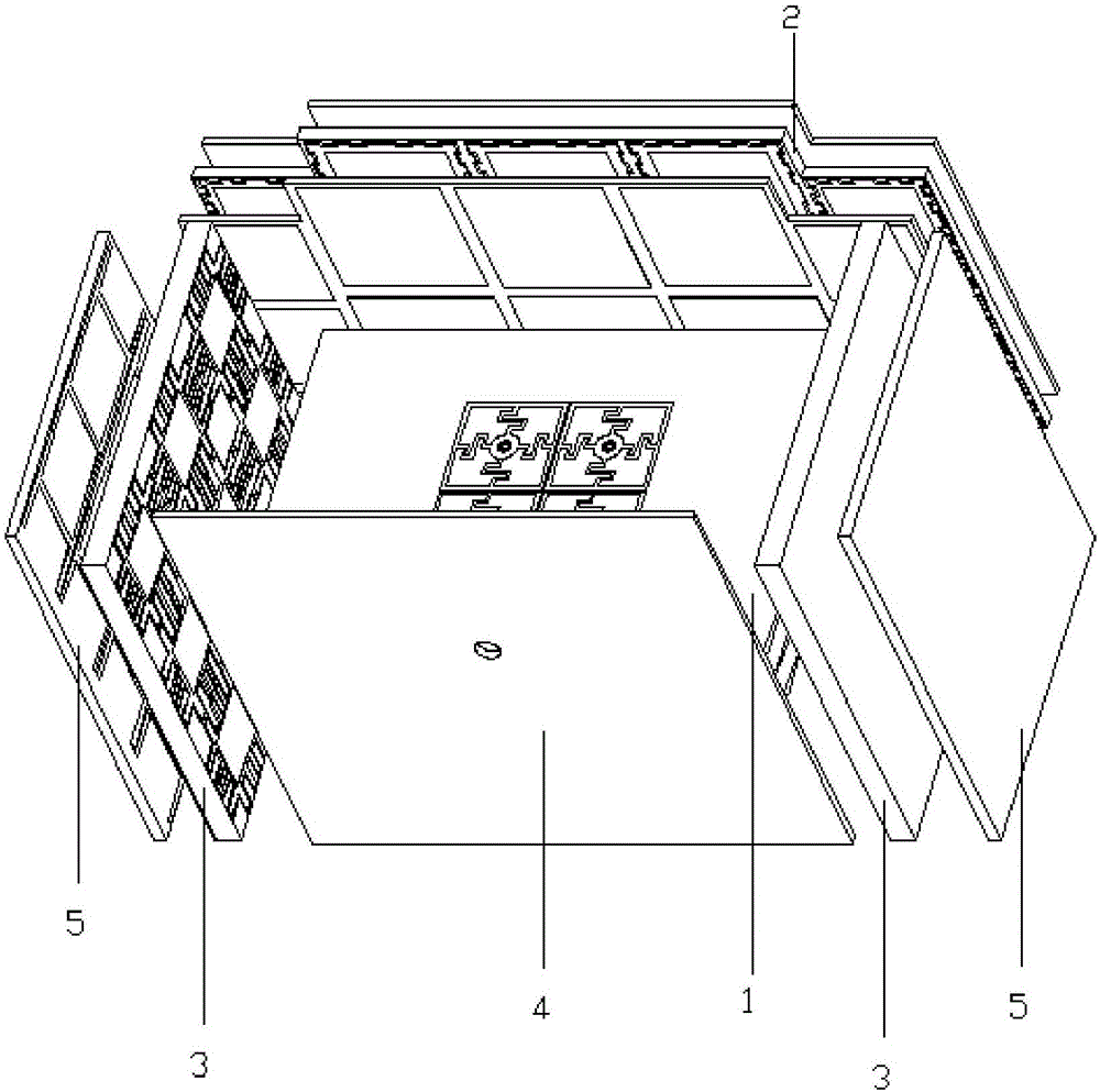
[0057] see figure 1 , the antenna provided by Embodiment 1 of the present invention includes a radiator 1, a director 2, one or two absorbers 3 and a reflector 4, and relative to the radiation direction of the radiator 1, the director 2 is located at the side of the radiator 1 In the front, the reflector 4 is located behind the radiator 1, and the two absorbers 3 are respectively located on the two sides of the radiator 1.
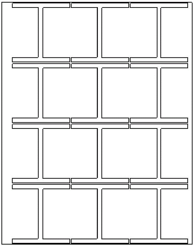
[0058] The antenna provided in Embodiment 1 of the present invention may also include one or two isolators 5, and the two isolators 5 are respectively located at the back of the two absorbers 3 facing away from the radiator 1, or at the back of the two absorbers 3 facing the radiation the front of device 1. Isolator 5 can adopt I-shaped single negative dielectric constant material (such as figure 2 shown). The reflector 4 in the antenna provided in Embodiment 1 of the present invention may be a metal plate.
[0059] see Figure 3 to Figure 6 The radi...
Embodiment 2
[0091] see Figure 15 The difference between the antenna provided by Embodiment 2 of the present invention and the antenna provided by Embodiment 1 of the present invention is that a director 6 of another structure and a reflector 7 of another structure are used.
[0092] see Figure 16 to Figure 22The director of the antenna working in the 5.8GHz frequency band provided by Embodiment 2 of the present invention includes a zero-refractive index lens 51 and one or two FSS lenses 52 in the director of the antenna provided by Embodiment 1 of the present invention. The period of the resonant screen unit structure of the FSS lens 52 in the second embodiment of the present invention and the period of the capacitive metal patch of the first capacitive screen and the second capacitive screen can be compared with that of the 2.4GHz frequency band in the first embodiment of the present invention The period of the FSS lens is less, depending on the actual situation. The zero-refractive-...
PUM
 Abstract
Description
Claims
Application Information