Power switch cabinet with directional fire extinguishing function

A power switch and functional technology, applied in substation/switch layout details, substation/switchgear cooling/ventilation, electrical components, etc., can solve the problems of cabinet door staff obstruction, accidents, shortened service life, etc., to avoid heat dissipation Too poor, prevent rainwater seepage, reduce the effect of space occupation

Inactive Publication Date: 2017-01-04
STATE GRID CORP OF CHINA +1
View PDF5 Cites 12 Cited by
  • Summary
  • Abstract
  • Description
  • Claims
  • Application Information

AI Technical Summary

Problems solved by technology

The switchgear is generally installed outdoors, and the interior of the switchgear is usually integrated with a large number of electrical component modules and various discrete electronic components that generate heat. If the internal temperature of the switch cabinet is too high, it will seriously affect the control accuracy and control stability, and even cause the electrical components to burn out, causing accidents.
The existing measures are: during the peak period of electricity consumption, open the door of the box and use an electric fan or install a cabinet fan to cool down. Some internal heating elements cannot be blown by the fan, so it is not easy to dissipate heat. Poor heat dissipation will cause the components to be overloaded and burn. Moreover, because the switchgear is charged and has many plastic parts, once it burns, it is easy to spread with the line. cause large economic losses
In the prior art, the fire extinguishing area of ​​the switchgear with fire extinguishing function is too large, which often affects the normal use of the entire switchgear; and when the door is opened, the door is easy to hinder the staff and is inconvenient to use; cooling with a fan will cause problems. The problem of poor local heat dissipation

Method used


Image

  • Power switch cabinet with directional fire extinguishing function
  • Power switch cabinet with directional fire extinguishing function
  • Power switch cabinet with directional fire extinguishing function

Examples


Embodiment Construction

[0020] The following will clearly and completely describe the technical solutions in the embodiments of the present invention with reference to the accompanying drawings in the embodiments of the present invention. Obviously, the described embodiments are only some, not all, embodiments of the present invention. Based on the embodiments of the present invention, all other embodiments obtained by persons of ordinary skill in the art without making creative efforts belong to the protection scope of the present invention.

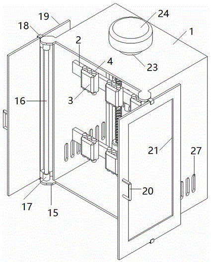
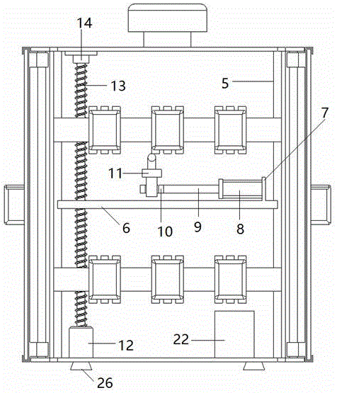
[0021] see Figure 1-7 , the present invention provides a technical solution: including a cabinet body 1, a plurality of connection plates 2 are evenly arranged on the inner wall of the middle part of the cabinet body 1, and a plurality of power switches 3 are uniformly installed on the connection plate 2, and both ends of the power switch 3 are arranged There are terminal posts 4, and the inner walls on both sides of the rear end of the cabinet body 1 are ver...


PUM


Abstract

The invention discloses a power switch cabinet with a directional fire extinguishing function. The power switch cabinet comprises a cabinet body, wherein a plurality of connecting plates are uniformly arranged on the inner wall of the middle part of the cabinet body; a plurality of power switches are uniformly arranged on the connecting plates; wiring terminals are respectively arranged at the two ends of each power switch; slide rails are vertically arranged on the inner walls of the two sides of the back end of the cabinet body; a slide plate is horizontally arranged at the back end of the cabinet body and is matched with the slide rails; a bulge is arranged at one end of the slide plate, and a hydraulic cylinder is horizontally arranged at one side of the bulge. The power switch cabinet has the advantages that a high-pressure spray head is controlled by a driving motor and a bidirectional screw rod to move along the vertical direction, and is controlled by a hydraulic cylinder and a piston rod to move along the horizontal direction, the high-pressure spray head can be quickly and accurately moved to the fire location, the enough liquid carbon dioxide is sprayed to extinguish the fire source, and the influence to the other positions of the cabinet body is reduced; by adopting the combination of a rotary shaft and a groove which is in a shape like Chinese character of hui, a cabinet door is slide along the groove in the shape like Chinese character of hui, the space occupation is reduced, and the convenience in use is realized.

Description

technical field [0001] The invention relates to the technical field of electric equipment, in particular to an electric switchgear with a directional fire extinguishing function. Background technique [0002] The switchgear is divided into power switchgear (box), lighting switchgear and metering box, and is the final equipment of the power distribution system. Switchgear is a general term for power supply control centers. The switchgear is used in the occasions where the load is scattered and there are few circuits; the power supply control center is used in the occasions where the load is concentrated and there are many circuits. They distribute the electric energy of a certain circuit of the upper-level power distribution equipment to the nearest load. This level of equipment shall provide protection, monitoring and control of the load. The switchgear is generally installed outdoors, and the interior of the switchgear is usually integrated with a large number of electri...

Claims


Application Information

Patent Timeline
Patent Type & Authority Applications(China)
IPC IPC(8): H02B1/30H02B1/28H02B1/56A62C3/16
CPCA62C3/16H02B1/28H02B1/30H02B1/565
Inventor 孙建涛王大军姜玉玺王芳郑伟张文韬张一荻从旭日王承方邢浩王爱心张蕊
Owner STATE GRID CORP OF CHINA
Why Eureka
Try Eureka