A Microstrip Rectifier Circuit Based on Dual-frequency Impedance Matching

A technology of impedance matching circuit and rectifier circuit, which is applied in the direction of circuit devices, irreversible AC power input conversion to DC power output, electrical components, etc., can solve the problems of large size, low efficiency, small bandwidth, etc., to reduce the size of the circuit, Efficient size matching and the effect of increasing the output voltage

Active Publication Date: 2019-08-02
SYSU CMU SHUNDE INT JOINT RES INST +1
View PDF3 Cites 0 Cited by
  • Summary
  • Abstract
  • Description
  • Claims
  • Application Information

AI Technical Summary

Problems solved by technology

The frequency distribution that can be collected and utilized is very wide, but the traditional radio frequency rectification circuit usually only works in one frequency band, in addition, the bandwidth is small, the efficiency is low, and the size is large. Therefore, it is necessary to design a radio frequency rectification circuit that can work in multiple frequency bands and high bandwidth is very meaningful

Method used


Image

  • A Microstrip Rectifier Circuit Based on Dual-frequency Impedance Matching
  • A Microstrip Rectifier Circuit Based on Dual-frequency Impedance Matching
  • A Microstrip Rectifier Circuit Based on Dual-frequency Impedance Matching

Examples


Embodiment 1

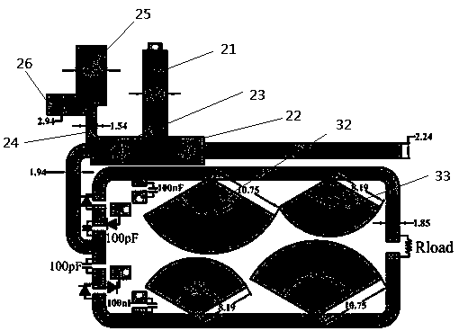
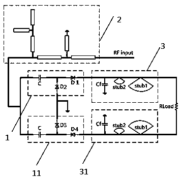
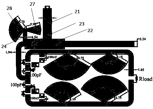
[0030] Such as figure 1 , 2 As shown, the microstrip rectification circuit based on dual-frequency impedance matching includes a rectification circuit 1, and also includes an input connector, a dual-frequency impedance matching circuit 2 and a harmonic suppression circuit 3. The rectification circuit 1 includes two rectification branches 11, The harmonic suppression circuit 3 includes two harmonic suppression branches 31, the output ends of the two rectification branches 11 are respectively connected to the input ends of the two harmonic suppression branches 31; The input end of the impedance matching circuit 2 is connected, and the output end of the dual-frequency impedance matching circuit 2 is respectively connected with the input ends of the two rectification branches 11 .

[0031] In the above solution, due to the addition of the dual-frequency impedance matching circuit 2, the rectification circuit 1 can achieve impedance matching in two frequency bands, so the rectific...

Embodiment 2

[0042] In this embodiment, the S11 parameters of the rectifier circuit provided in Embodiment 1 are tested, and the specific test results are as follows Figure 5 , 6 As shown, it can be seen from the figure that the operating frequency of the dual-frequency microstrip rectifier circuit is 875MHz and 1.83GHz, and the return loss (S11) at these two frequencies can reach a local minimum, that is, the dual-frequency impedance matching network can simultaneously Impedance matching is realized at the corresponding working frequency, and the energy input corresponding to the working frequency is maximized.


PUM


Abstract

The invention relates to a dual frequency impedance matching based microstrip rectifier circuit, comprising a rectifier circuit, an input connector, a dual frequency impedance matching circuit and a harmonic wave suppression circuit. The rectifier circuit includes two rectification branches; the harmonic wave suppression circuit includes two harmonic wave suppression branches; the output ends of the two rectification branches are connected with the input ends of the two harmonic wave suppression branches respectively. The output end of the input connector is connected with the input end of the dual frequency impedance matching circuit and the output end of the dual frequency impedance matching circuit is connected with the input ends of the two rectification branches respectively. Compared with the prior art, the circuit of the invention is advantageous as follows: 1) the adoption of improved [pai]-shaped microstrip matching method achieves a dual-frequency matching effect and improves the energy utilization efficiency; 2) the arrangement of symmetrical differential structures and the capacitors in parallel suppress the second harmonic waves, reduce the size of the circuit, and improve the integration; and 3) the use of a four-times differential rectifier circuit improves the output voltage of a DC load.

Description

technical field [0001] The present invention relates to the field of wireless energy transmission, in particular to a microstrip rectifier circuit based on dual-frequency impedance matching. Background technique [0002] Wireless energy transmission technology refers to the technology in which electric energy is not transmitted through physical wires, but uses microwaves for wireless transmission. Microwave energy has been extensively researched due to its advantages of mobility, greenness and freeness, and not being affected by the day and night environment. With the development of semiconductor technology, etc., wireless energy transmission technology has been widely developed in the field of low-power applications, especially in portable wireless electronic devices and the like. [0003] Wireless communications between wireless devices, such as wireless telecommunication base stations and mobile phones, flood the surrounding environment with RF energy. Therefore, wasted...

Claims


Application Information

Patent Timeline
Patent Type & Authority Patents(China)
IPC IPC(8): H02M7/02H02M7/06H02J50/00H02J3/01
CPCH02J3/01H02M1/14H02M7/02H02M7/06Y02E40/40
Inventor 谭洪舟黎梓宏曾淼旺刘先泺李宇廖肇荣曾衍瀚
Owner SYSU CMU SHUNDE INT JOINT RES INST
Why Eureka
Try Eureka