Digital pulse width modulator based on delayed phase modulation

A technology of width modulation and digital pulse, applied in the field of electronics, can solve the problems of complex structure, high cost, high design process requirements, etc., and achieve the effect of simple design, easy implementation and low cost

Inactive Publication Date: 2017-01-04
NANJING UNIV OF SCI & TECH +1
View PDF3 Cites 11 Cited by
  • Summary
  • Abstract
  • Description
  • Claims
  • Application Information

AI Technical Summary

Problems solved by technology

However, this method has the following disadvantages: the basic clock signal frequency of this method is only

Method used


Image

  • Digital pulse width modulator based on delayed phase modulation
  • Digital pulse width modulator based on delayed phase modulation
  • Digital pulse width modulator based on delayed phase modulation

Examples


Embodiment Construction

[0021] The present invention will be described in further detail below with reference to the accompanying drawings.

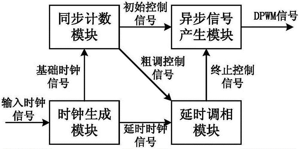
[0022] The present invention provides a digital pulse width modulator based on delay phase modulation, such as figure 1 As shown, the modulator is composed of a clock generation module, a synchronous counting module, a delay phase modulation module and an asynchronous signal generation module. The specific circuit diagram of the four modules is as follows: Figure 2 to Figure 5 shown.

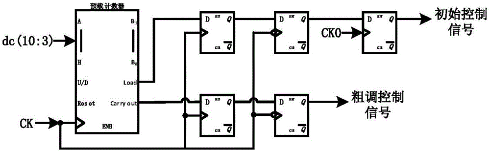
[0023] Firstly, the input 11-bit array dc(10:0) is divided into high 8-bit array N=dc(10:3) and low 3-bit array m=dc(2:0).

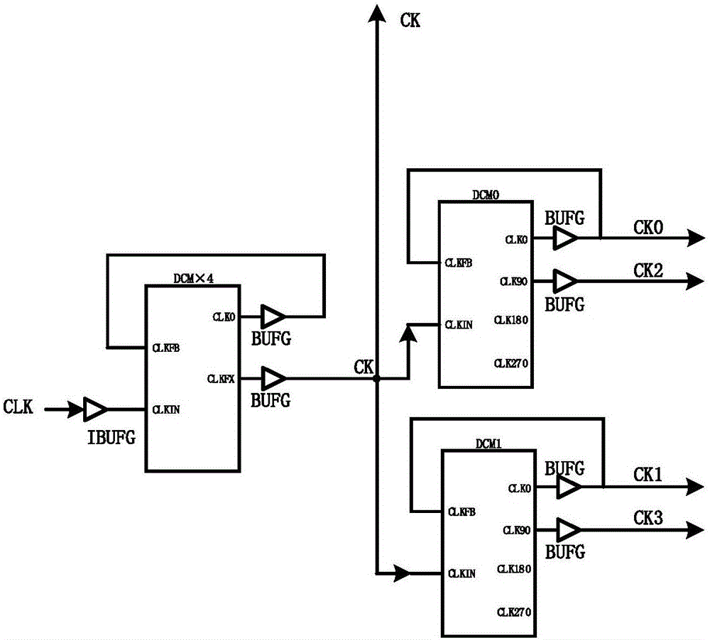
[0024] exist figure 2 In the shown clock generation module, DCM×4 is a frequency multiplier of 4 times, and DCM0 and DCM1 are two digital clock supervisors. The CLK signal is an input clock signal with a frequency of 50MHz. After the CLK clock signal is spread by a DCM×4 frequency multiplier, a basic clock signal CK with a frequency of 200MHz is obta...


PUM


Abstract

The invention discloses a digital pulse width modulator based on delayed phase modulation. The digital pulse width modulator is composed of a clock generating module, a synchronous counting module, a delayed phase modulation module and an asynchronous signal generating module. The clock generating module performs frequency multiplication on an input clock signal and outputs a fundamental clock signal to the synchronous counting module, simultaneously delays the fundamental clock signal and outputs the delayed clock signal to the delayed phase modulation module. The synchronous counting module finishes coarse adjustment of the pulse width and respectively outputs an initial control signal and a coarse-adjusted control signal to the asynchronous signal generating module and the delayed phase modulation module. The delayed phase modulation module delays the coarse-adjusted control signal for generating eight paths of termination control signals and selects one path of termination control signal for outputting to the asynchronous signal generating module. The initial control signal and the termination control signal are input into an RS trigger in the asynchronous signal generating module and a final DPWM signal is output. The digital pulse width modulator improves modulation precision on the condition of no fundamental clock signal change and furthermore has advantages of relatively high accuracy, high versatility and high applicability.

Description

technical field [0001] The invention belongs to the field of electronic technology, and in particular relates to a digital pulse width modulation circuit. Background technique [0002] In the system structure using digital pulse width modulation (Digital Pulse Width Modulation, DPWM), the main methods currently used are hybrid DPWM (Hybrid DPWM), and the second is DPWM realized by Dither method. The DPWM implemented by the Dither method is mainly realized by the idea of ​​​​the design. This design can use a low-precision and high-frequency DPWM to achieve a high effective output accuracy, which also reduces the power consumption and area of ​​​​the DPWM. However, the DPWM realized by the Dither method will generate a cycle delay when the mode is switched, which is not good for the high-speed response of the DPWM. Hybrid DPWM designs have no unwanted delays. [0003] The hybrid DPWM combines the traditional counter structure and the delay chain structure, and is usually com...

Claims


Application Information

Patent Timeline
IPC IPC(8): H03K7/08
CPCH03K7/08
Inventor 李洪涛张巍巍胡姗姗庄珊娜戴祥冯欣齐全陆晓明匡鑫朱金瑞
Owner NANJING UNIV OF SCI & TECH
Why Eureka
Try Eureka