A high-precision patch head with flight recognition function

A high-precision, patch head technology, used in printed circuits, electrical components, printed circuit manufacturing, etc., can solve the problems of limiting the number of identifiable nozzles, complex optical path matching, and large patch head volume, so as to facilitate noise reduction processing. , The effect of large design and easy installation

Active Publication Date: 2019-04-02
江苏华志珹智能科技有限公司
View PDF12 Cites 0 Cited by
  • Summary
  • Abstract
  • Description
  • Claims
  • Application Information

AI Technical Summary

Problems solved by technology

Both of the above-mentioned latest technologies have obvious defects. One will limit the number of identifiable nozzles, and the other is more complex in optical path matching, and both of them are costly, and the size of the patch head is relatively large. Therefore, a simple structure, miniaturization, Low-cost placement heads with flight recognition function urgently need to be developed

Method used


Image

  • A high-precision patch head with flight recognition function
  • A high-precision patch head with flight recognition function
  • A high-precision patch head with flight recognition function

Examples


Embodiment Construction

[0027] The specific embodiment of the present invention will be further described below in conjunction with accompanying drawing:

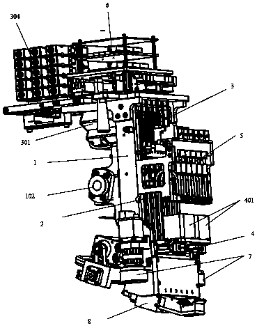
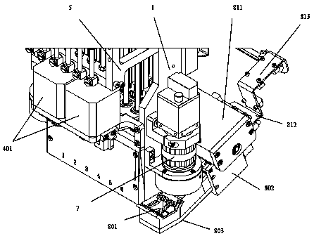
[0028] Such as Figure 1-7As shown, a high-precision placement head with flight recognition function includes a placement head support 1, a plurality of placement axes 2 installed in the placement head support 1, and a Z-direction lift that drives the placement axis 2 to rise and fall. Mechanism 3. The R-direction corner mechanism that drives the placement shaft 2 to rotate in a circle. The front is equipped with a vacuum module 5, and its front middle part is equipped with an R-direction stepper motor 401 for driving the R-direction corner mechanism 4 and a CCD camera 7 for collecting images, and a Z-direction drive motor 301 is installed on its back top, and the Z-direction The direction of the output axis of the drive motor 301 is perpendicular to the Z axis; the lower part of the back of the mounting head bracket 1 is equipped with a flying c...


PUM


Abstract

The invention provides a high-precision chip mounting head capable of flight identification. The chip mounting head comprises a chip mounting head support, chip mounting shafts mounted in the chip mounting head support, a direction-Z elevation mechanism, a direction-R turning mechanism and a vacuum module group; the chip mounting head is characterized in that an integrated control assembly is mounted in the back side of the upper portion of the chip mounting head support, the vacuum module group is mounted in the front side of the upper portion of the support, a direction-R stepping motor which drives the direction-R turning mechanism and a CCD camera collecting images are mounted in the middle of the front side of the support, direction-Z driving motors are mounted in the back side of the support, and the directions of output shafts of the direction-Z driving motors are vertical to the axis-Z; and a flight camera device is mounted in the lower portion of the back side of the chip mounting head support, and comprises a light source assembly below a nozzle, a camera assembly, a camera support provided with the light source assembly and the camera assembly and a driving mechanism which enables the camera support to move along the axis-X, and an acute angle is formed between the direction of a lens of the camera assembly and the vertical direction in the XY plane. The chip mounting head is minimized and low-cost, and stable, accurate, rapid and high-precision chip mounting is realized.

Description

technical field [0001] The invention relates to a placement head, in particular to a placement head with high precision and flight recognition function. Background technique [0002] At present, there are many kinds of placement machines, but whether it is a fully automatic high-speed placement machine or a manual low-speed placement machine, its overall layout is similar. The fully automatic placement machine is controlled by a computer and is a high-precision automation equipment integrating optics, mechanics and electronics. The identification system is composed of sensors and computer control system, which includes the functions of picking-displacement-positioning-placement, etc., and realizes the fast and accurate placement of SMD components. As an important part of the whole machine, the placement head of the placement machine is very critical to the performance of the whole machine. After picking up the components, the placement head can automatically correct the pos...

Claims


Application Information

Patent Timeline
Patent Type & Authority Patents(China)
IPC IPC(8): H05K3/30
CPCH05K3/30H05K2203/085H05K2203/163
Inventor 吴志达程治国吴凡
Owner 江苏华志珹智能科技有限公司
Why Eureka
Try Eureka