
Mounting head control system and method

A control system and control method technology, which is applied in the direction of assembling printed circuits with electrical components, can solve the problems of complex control system and method, complex structure, etc., and achieve the effects of facilitating noise reduction processing, increasing suction speed, and reducing fluctuations

Active Publication Date: 2017-01-04
广东木几智能装备有限公司
View PDF5 Cites 5 Cited by
  • Summary
  • Abstract
  • Description
  • Claims
  • Application Information

AI Technical Summary

Problems solved by technology

However, this complex structure makes the control system and method complicated. Therefore, it is necessary to conduct research to provide a chip head control system and method with simplified control system, convenient operation, low manufacturing cost and convenient maintenance.

Method used


Image

  • Mounting head control system and method
  • Mounting head control system and method
  • Mounting head control system and method

Examples


Embodiment

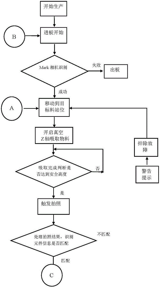
[0034] Example: There are currently 6 points, and the distances from head 1 are 21 8.9 6.2 15 5 22 , so the final action is

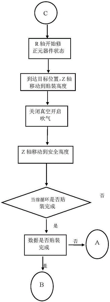
[0035] (1) R1 starts to modify the shape of the 1-axis component, and the 1-axis starts to mount.

[0036] (2) After the 1-axis mounting is completed, it starts to rise, and R2 starts to correct the shape of the 2-axis components.

[0037] (3) After the 2-axis placement is completed, it starts to rise, and R1 starts to correct the shape of the 3-axis components.

[0038] (4) After the 3-axis placement is completed, it starts to rise, and R2 starts to correct the shape of the 4-axis components.

[0039] (5) After the 4-axis placement is completed, it starts to rise, and R1 starts to correct the shape of the 5-axis components.

[0040](6) After the 5-axis placement is completed, it starts to rise, and R2 starts to correct the shape of the 6-axis components.

[0041] (7) After the 6-axis placement is completed, it rises to a safe height, R1R2 returns to...


PUM


Abstract

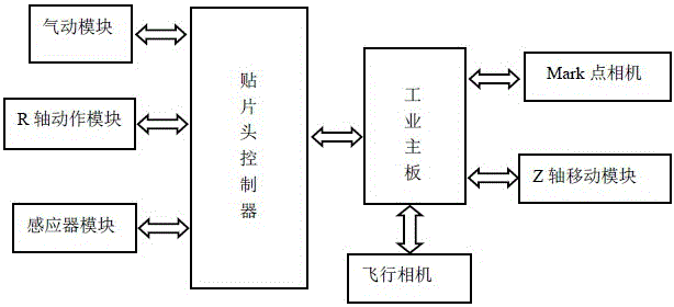
The invention provides a mounting head control system. The mounting head control system consists of a mounting head controller, an industrial mainboard, a Mark point camera, a Z axis moving module, a flight camera, a pneumatic module, an R axis motion module and an inductor module. The mounting head control system is characterized in that the Mark point camera, the Z axis moving module and the flight camera are connected to the industrial mainboard; the mounting head controller is connected to the pneumatic module, the R axis motion module and the inductor module; and the mounting head controller is connected to the industrial mainboard. The mounting head control system and method use a modularization idea and use a mounting head controller to be connected to the industrial mainboard, independently take charge for data processing of the pneumatic module, the R axis motion module and the inductor module, realize material absorbing and discharging of a mounting shaft, and member rotation in an R direction; the inductor is in charge of data collection of the pneumatic module and the R axis motion module and is in communication with the industrial mainboard through a CAN bus, which makes the whole system faster and more efficient. The mounting head control system and method effectively improve a material absorbing speed, reduce vacuum detection fluctuation and provide convenience to noise reduction processing of a detection signal of a simulation pressure sensor.

Description

technical field [0001] The invention relates to an automatic control system and method of a multifunctional placement machine, in particular to a control system and method of a placement head. Background technique [0002] Using high-speed placement technology to install integrated circuit components on PCB boards is an important way to improve installation efficiency and installation accuracy. The placement head is one of the most critical equipment of the placement machine, which directly affects the speed and accuracy of placement. [0003] At present, the placement head used by foreign high-speed placement machines is usually composed of a placement shaft, a linear bearing, a jacket, a synchronous pulley, a bearing, a servo motor, etc., and the placement shaft is made in the form of a spline shaft, and its outer side is opened symmetrically. The two arc grooves of the linear bearing are matched with the balls in the linear bearing to realize the infinite linear motion u...

Claims


Application Information

Patent Timeline
IPC IPC(8): H05K3/30
CPCH05K3/30
Inventor 吴志达程治国吴凡
Owner 广东木几智能装备有限公司
Learn More