
Liquid drop discharging apparatus and liquid drop discharging method

A discharge device, droplet technology, applied to the surface coating liquid device, spray device, coating, etc., can solve the problem of positional relationship changes

Active Publication Date: 2017-01-11
TOKYO ELECTRON LTD
View PDF6 Cites 17 Cited by
  • Summary
  • Abstract
  • Description
  • Claims
  • Application Information

AI Technical Summary

Problems solved by technology

[0005] However, in the process of moving the workpiece stage toward the functional droplet ejection head after the alignment of the workpieces, due to the deviation of the direction of the workpiece, the mechanical accuracy of the moving mechanism of the workpiece stage, temperature changes, and changes over time, There is a problem that the positional relationship between the functional droplet discharge head and the bank on the workpiece changes due to reasons such as

Method used


Image

  • Liquid drop discharging apparatus and liquid drop discharging method
  • Liquid drop discharging apparatus and liquid drop discharging method
  • Liquid drop discharging apparatus and liquid drop discharging method

Examples


no. 1 Embodiment approach

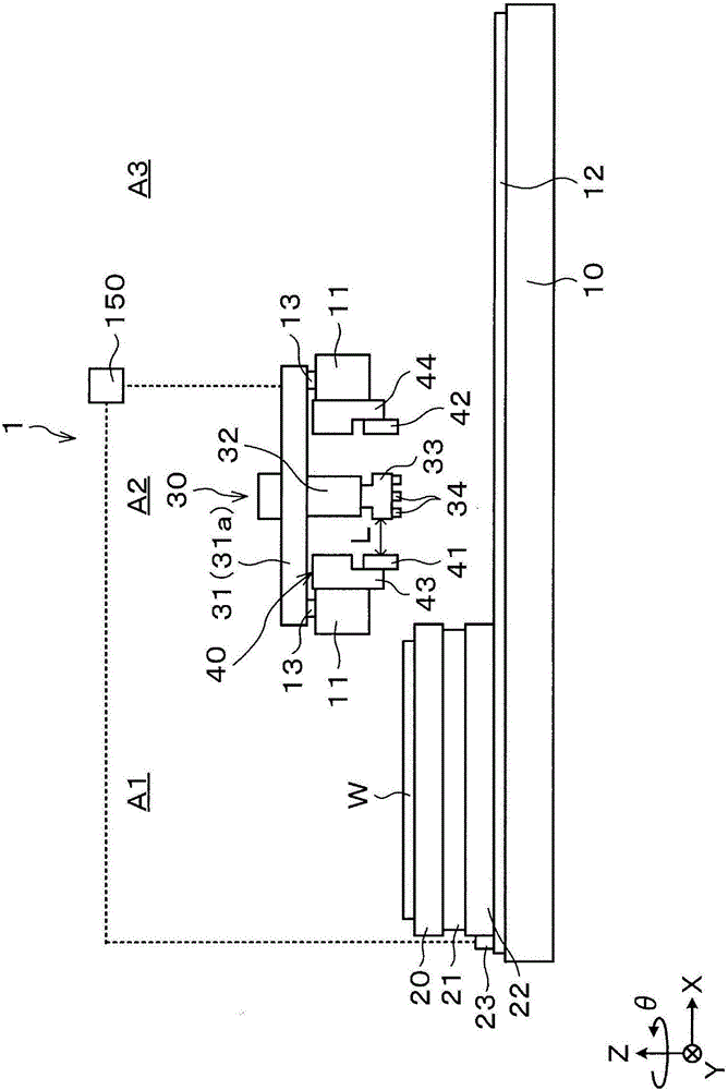
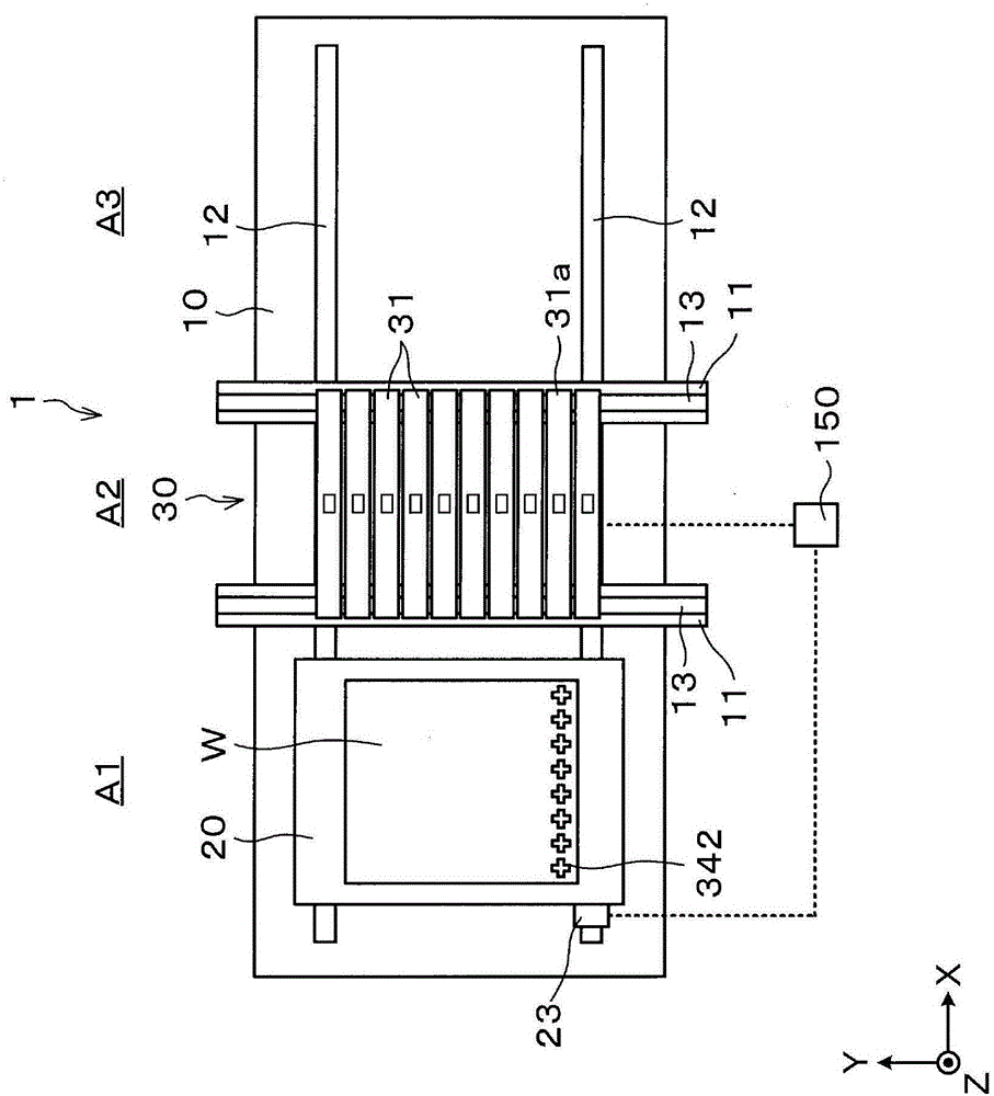
[0036] First, refer to figure 1 and figure 2 The configuration of the droplet discharge device according to the first embodiment of the present invention will be described. figure 1 It is a schematic side view showing a schematic configuration of the droplet ejection device 1 . figure 2 It is a schematic plan view showing a schematic configuration of the droplet ejection device 1 . In addition, in the following, let the main scanning direction of the workpiece W be the X-axis direction, the sub-scanning direction perpendicular to the main scanning direction be the Y-axis direction, and the vertical direction perpendicular to the X-axis direction and the Y-axis direction be the Z-axis direction. , The direction of rotation around the Z-axis direction is the θ direction.

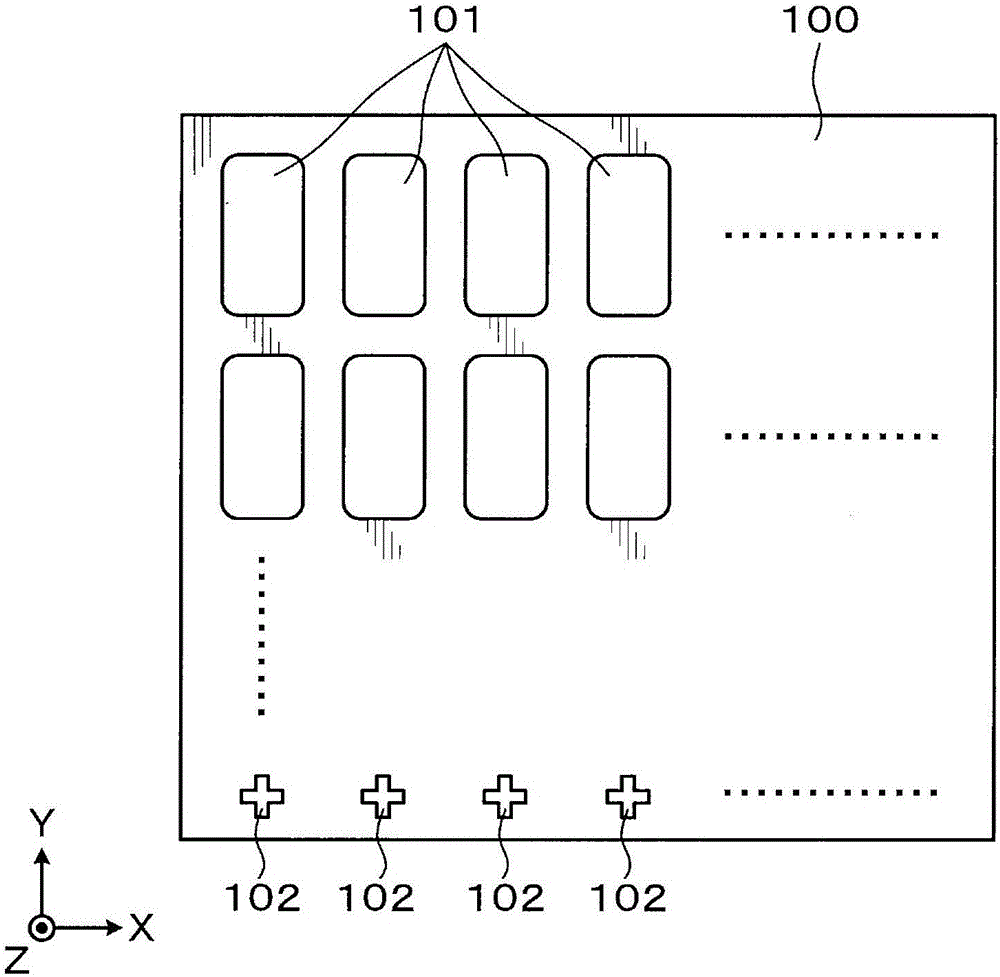
[0037] In addition, the workpiece W used in the present invention, such as image 3 As shown, a dike portion 100 is formed as a partition wall. The bank portion 100 is patterned into a predetermined pat...

Embodiment approach

[0079] According to the above-mentioned first embodiment, it includes: the movement amount detection mechanism 23 that detects the movement amount of the workpiece mounting table 20 in the X-axis direction (main scanning direction); The first imaging unit 41 of the captured image F; the image processing unit 160 that detects the reference mark 102 based on the captured image F; Therefore, in the workpiece movement control unit 162, the difference between the detected position of the reference mark 102 and the position of the reference mark 102 estimated by the mark position estimation unit 161 can be obtained. Then, in the workpiece movement control unit 162, if the difference is equal to or greater than a threshold value, it is determined that the position of the reference mark 102 detected at the imaging position deviates from the position of the reference mark 102 estimated by the mark position estimation unit 161. For example, The operation of the workpiece mounting table ...

no. 2 Embodiment approach

[0089] Next, a second embodiment of the present invention will be described. In addition, the droplet discharge device 1 used in the second embodiment is the same as the droplet discharge device 1 used in the first embodiment.

[0090] In the first embodiment, the position of the reference mark 102 of the workpiece W is detected, and so-called feedforward control is performed on the same workpiece W based on the position information of the reference mark 102. A case where the trend of deviation is common among workpieces. In this case, for example, correction data obtained when processing the K-th (K is a positive integer) workpiece W may be reflected in the processing of the K+1-th workpiece W. FIG.

[0091] Specifically, such as Figure 12 As shown, in the workpiece movement control unit 162 , before processing the K+1-th workpiece W, the correction position of the K-th workpiece W is collected in advance. In addition, in Figure 12 In , the offset in the Kth workpiece W...


PUM


Abstract

The invention provides a liquid drop discharging apparatus which enables a functional liquid drop discharging head and a dyke part on a workpiece to be precisely aligned. The liquid drop discharging apparatus (1) comprises a liquid drop discharging head (34), a workpiece carrying bench (20) and a first shooting device (41). When a workpiece (W) is moved by a specified distance in a main scanning direction (X-axis direction), the position of a reference mark formed on the workpiece (W) is detected based on an image captured by the first shooting device (41), the position of the reference mark is predicted based on displacement of the workpiece carrying bench (20) detected by a displacement detection mechanism (23), then a relative position of the workpiece (W) and the liquid drop discharging head (34) is corrected based on the correlation between the position of the reference mark detected based on the image and the position of the reference mark predicted based on displacement of the workpiece carrying bench (20). Therefore, the functional liquid drop discharging head and the dyke part on the workpiece can be precisely aligned.

Description

technical field [0001] The present invention relates to a droplet discharge device that discharges and draws droplets of a functional liquid onto a workpiece, and a droplet discharge method using the droplet discharge device. Background technique [0002] Conventionally, an inkjet type liquid drop discharge device that discharges the functional liquid as liquid droplets is known as a device that uses a functional liquid to draw on a workpiece. Droplet discharge devices are used, for example, in the manufacture of electro-optical devices (flat panel displays: FPDs) such as organic EL devices, color filters, liquid crystal display devices, plasma displays (PDP devices), electron emission devices (FED devices, SED devices), etc. being widely used. [0003] The droplet discharge device includes, for example: a functional droplet discharge head that discharges droplets of the functional liquid; a workpiece mounting table on which a workpiece is placed; and a direction in which t...

Claims


Application Information

Patent Timeline
Patent Type & Authority Applications(China)
IPC IPC(8): B05B13/02B41J2/01
CPCB05B13/0221B05B13/0278B41J2/01B05C5/0258B05C11/1005G02B5/223G02F1/1303H01J9/025H10K71/135
Inventor 吉富济尾上幸太朗筱崎贤哉
Owner TOKYO ELECTRON LTD
Features
  • Generate Ideas
  • Intellectual Property
  • Life Sciences
  • Materials
  • Tech Scout
  • Unparalleled Data Quality
  • Higher Quality Content
  • 60% Fewer Hallucinations
Learn More