Die-forming method taking non-maximal cross section as die parting face based on combined die

A technology of combining dies and cross-sections, which is used in manufacturing tools, forging/pressing/hammer devices, forging/pressing/hammering machines, etc. The effect of small machining volume, improved material utilization rate, and improved production efficiency

Active Publication Date: 2017-01-11
TSINGHUA UNIV
View PDF7 Cites 9 Cited by
  • Summary
  • Abstract
  • Description
  • Claims
  • Application Information

AI Technical Summary

Problems solved by technology

But this process also has two major disadvantages: 1. The blank for die forging needs to be made by free forging, which increases the cost to a certain extent
The forging force is too high to achieve the maximum cross-section die forging method

Method used


Image

  • Die-forming method taking non-maximal cross section as die parting face based on combined die
  • Die-forming method taking non-maximal cross section as die parting face based on combined die
  • Die-forming method taking non-maximal cross section as die parting face based on combined die

Examples


Embodiment

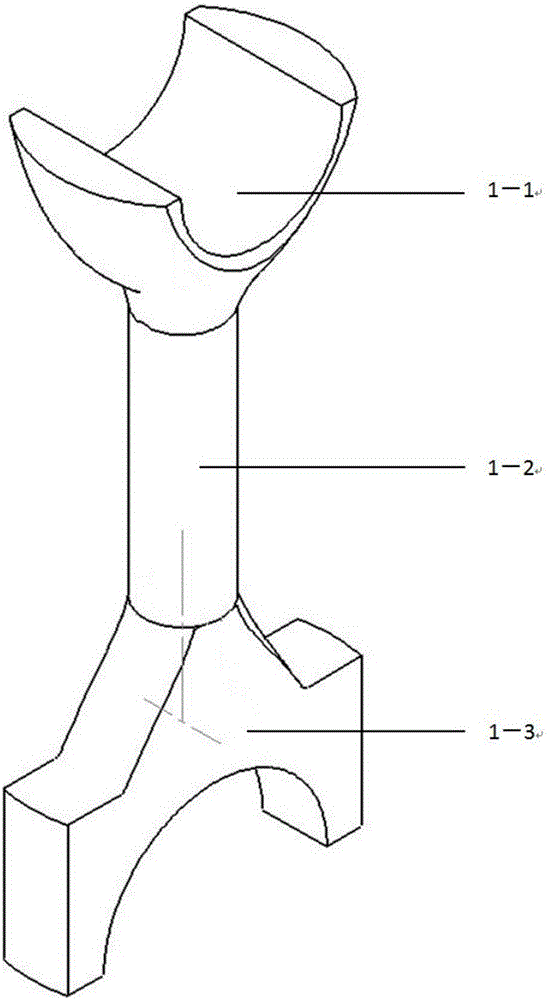
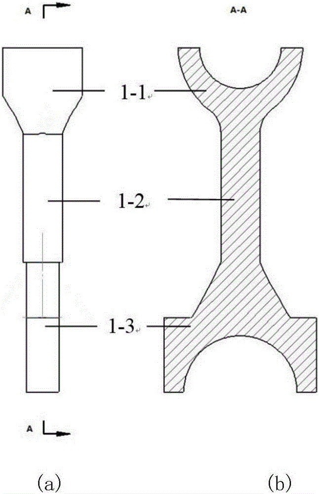
[0027] This embodiment is to produce a large-scale marine connecting rod by using the die forging method based on the combination die described in the present invention with the non-maximum cross-section as the parting surface. For the specific shape of the connecting rod, see figure 1 , for a large marine engine connecting rod. The marine connecting rod structure can be divided into three parts: the upper end is the small end of the connecting rod, which is a spherical structure 1-1 with a cylindrical inner surface, which is used to connect with the piston pin; the lower end is the large end of the connecting rod, which is a cylindrical inner surface. The square block structure 1-3 on the surface is used to connect with the crankshaft; the connecting rod body is a cylindrical structure 1-2 in the middle, which is connected between the big end and the small end of the connecting rod. The connecting rod is 3.2m in total length, 0.7m in the thickest part, and weighs more than 5 ...


PUM


Abstract

The invention relates to a die-forming method taking a non-maximal cross section as a die parting face based on a combined die. The die-forming method is characterized by comprising the following steps of adopting an upper die, a lower die and a detachable combined type die which consists of a plurality of side dies, selecting a corresponding board, which takes the non-maximal cross section of a middle-section axis of a long-axis variable-section forge piece as the die parting face for die-forming, as die-forming blank; and arranging the upper die and the lower die at the upper side and the lower side of the die parting face of the board blank, fixing the combined type die to the periphery of the board, moving away the combined type die after carrying out one heat die-forming, and taking out a workpiece. According to the die-forming method, die-forming load is effectively reduced by selecting the non-maximal cross section as the die parting face; follow-up machining amount is reduced by adopting a die-forming process, so that a material utilization rate is increased; the board is adopted as die-forming blank, so that blank preparing processes are reduced; one heat forming can be carried out, so that production efficiency is improved; and besides, the follow-up machining amount of the process is small, and comprehensive mechanical performances of the forge piece are improved without damaging a metal flow line.

Description

technical field [0001] The invention belongs to the technical field of forging, and in particular relates to a die forging process method of a long-axis type variable cross-section forging. Background technique [0002] Forgings with long-axis variable cross-section usually have a simple middle shape such as circle, ellipse, square, etc., and complex shapes at both ends. In the work, long-axis variable cross-section parts usually need to bear alternating loads such as compression, tension, and bending, so higher requirements are placed on the quality of forgings. Commonly used long-axis variable cross-section forgings such as connecting rods, crank throws, crankshafts, etc., but not limited to them. [0003] Due to the complex shape of the long-shaft variable cross-section forgings, the process of free forging + machining is usually used, and the die forging process with the largest cross-section as the parting surface is usually used for production. These two methods have...

Claims


Application Information

Patent Timeline
Patent Type & Authority Applications(China)
IPC IPC(8): B21J5/02B21J13/02B21K7/12
CPCB21J5/025B21J13/02B21K7/12
Inventor 吴任东袁朝龙武东文焦玮
Owner TSINGHUA UNIV
Why Eureka
Try Eureka