Non-sinusoidal vibration method of continuous casting mold

A continuous casting mold, non-sinusoidal technology, applied in the field of metallurgical continuous casting, can solve problems such as breakouts, cracks on the surface of billets, vibration marks, etc.

Active Publication Date: 2017-01-11
NORTHEASTERN UNIV
View PDF7 Cites 8 Cited by
  • Summary
  • Abstract
  • Description
  • Claims
  • Application Information

AI Technical Summary

Problems solved by technology

However, in the process of high-speed continuous casting slab production, surface cracks, vibration marks, and even breakout accidents will inevitably occur

Method used


Image

  • Non-sinusoidal vibration method of continuous casting mold
  • Non-sinusoidal vibration method of continuous casting mold
  • Non-sinusoidal vibration method of continuous casting mold

Examples


Embodiment Construction

[0031] Embodiments of the present invention will be further described in detail below in conjunction with the accompanying drawings.

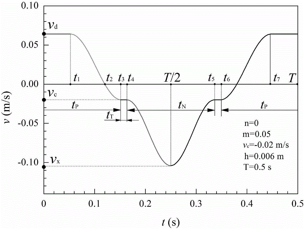
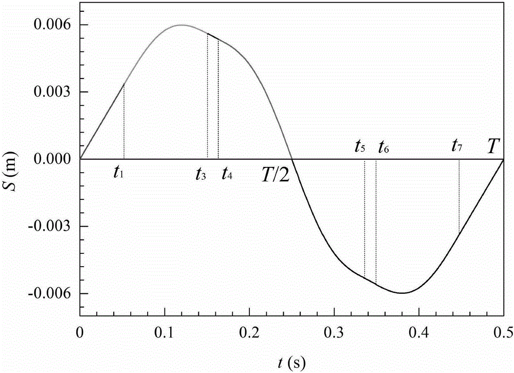
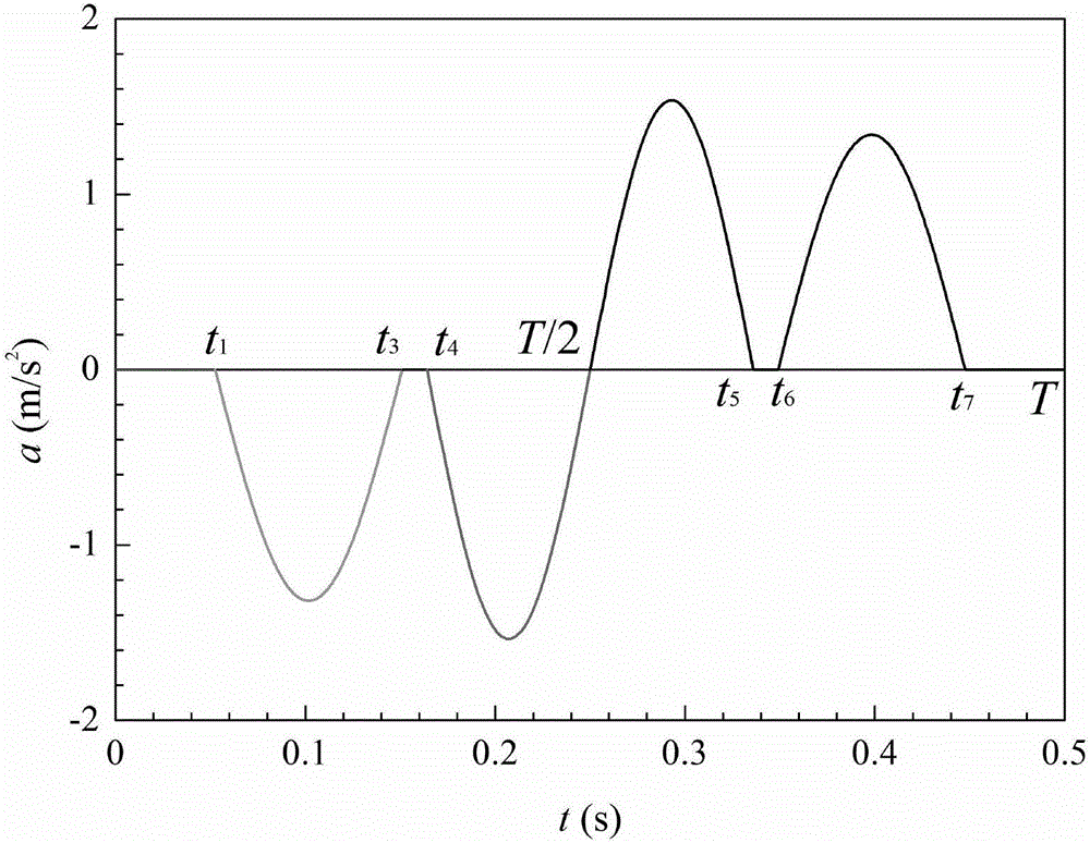
[0032] The specific process of the non-sinusoidal vibration method of the continuous casting mold is: control the driving device of the continuous casting mold, so that the continuous casting mold is driven by the driving device, and the eight-stage speed determined by the following eight-stage speed function in each vibration cycle The waveform vibrates non-sinusoidally:

[0033] v = v d ( 0 ≤ t ≤ t 1 ) v d ...


PUM


Abstract

The invention provides a non-sinusoidal vibration method of a continuous casting mold. The non-sinusoidal vibration method includes steps of controlling a driving device of the continuous casting mold so that the continuous casting mold vibrates non-sinusoidally in line with eight-stage speed determined as the following eight-stage speed function in each vibration cycle; introducing a new vibration control variable, namely the constant-speed duration factor m, increasing the control means for the waveforms to facilitate the vibration control according to the actual conditions. The casting speed and vibration waveform can be combined for different billet speed, and different vibration schemes can be designed; the consumption of casting powder can be increased, continuous casting lubrication is facilitated, and friction, cracks and binding are reduced. Therefore, the vibration speed of the crystallizer is equal to the extension of the casting speed, and the uniform outward heat transfer of the continuous casting and stable growth of the initial base are facilitated.

Description

technical field [0001] The invention belongs to the technical field of metallurgical continuous casting, and in particular relates to a non-sinusoidal vibration method of a continuous casting crystallizer. Background technique [0002] During the continuous casting slab production process, molten steel is completed in the continuous casting production line from solidification to forming. As the most important part of the continuous casting machine, the continuous casting mold plays an important role in cooling heat transfer, solidification forming, liquid steel purification and quality control of continuous casting slabs. During the molten steel casting process, the crystallizer vibrates according to certain rules to ensure the lubrication of the continuous casting slab and the mold wall, so as to prevent the steel breakout accident caused by the bonding of the initial solidification slab shell and the mold wall. With the continuous deepening of people's understanding of th...

Claims


Application Information

Patent Timeline
Patent Type & Authority Applications(China)
IPC IPC(8): B22D11/053B22D11/16
CPCB22D11/053B22D11/166
Inventor 孟祥宁朱苗勇汪宁周建川杨青山
Owner NORTHEASTERN UNIV
Why Eureka
Try Eureka