
Driving device and injection molding machine provided with driving device

A driving device and driver technology, applied in the field of injection molding machines, can solve the problems of high cost, rare cost of the motor, and high energy consumption, and achieve the effects of improving energy-saving characteristics, reducing the cost of the motor, and reducing the volume of the motor.

Active Publication Date: 2017-01-11
震雄机械(深圳)有限公司
View PDF5 Cites 1 Cited by
  • Summary
  • Abstract
  • Description
  • Claims
  • Application Information

AI Technical Summary

Problems solved by technology

[0005] The object of the present invention is to provide a driving device and an injection molding machine with the driving device, so as to solve the defects of high cost, high energy consumption and low efficiency of the traditional hydraulic motor drive, and at the same time avoid the limited input torque provided by the single motor drive, Rare motors and excessive cost

Method used


Image

  • Driving device and injection molding machine provided with driving device
  • Driving device and injection molding machine provided with driving device
  • Driving device and injection molding machine provided with driving device

Examples


Embodiment Construction

[0023] Typical embodiments that embody the features and advantages of the present invention will be described in detail in the following description. It should be understood that the present invention is capable of various changes in different embodiments without departing from the scope of the present invention, and that the description and illustrations therein are illustrative in nature and not limiting. this invention.

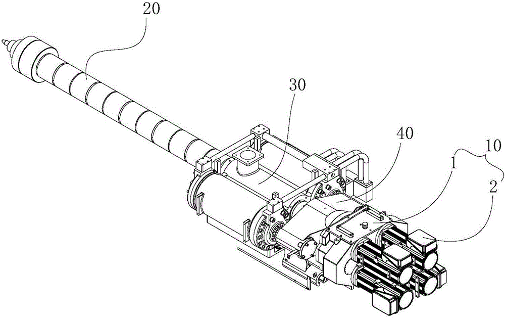
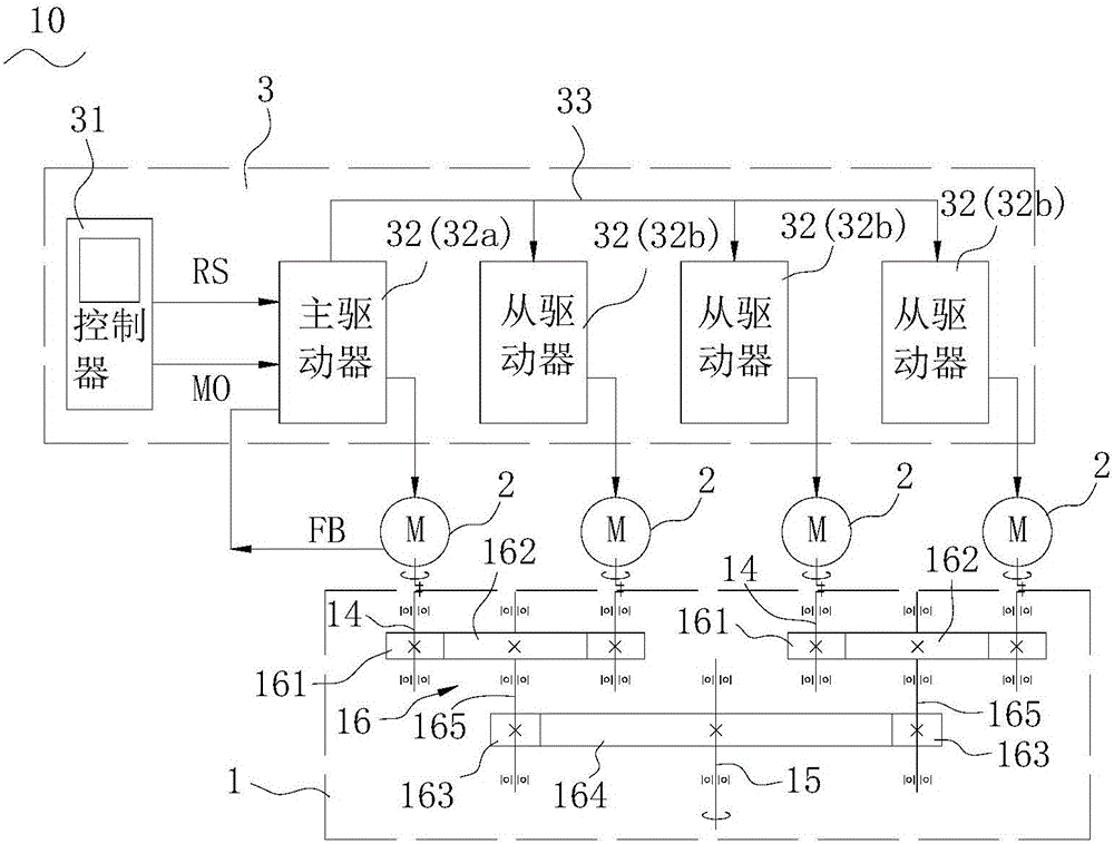
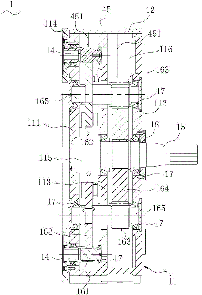
[0024] The invention provides a driving device and an injection molding machine with the driving device. Such as figure 1 As shown, in this embodiment, the driving device 10 includes a reducer 1 and four servo motors 2 mounted on the reducer 1 . Four servo motors 2 are used as driving sources, and the input of each servo motor 2 is decelerated by the reducer 1 and synthesized into a single-axis output. The injection molding machine is equipped with a material tube assembly 20, which is provided with a screw for melt injection molding. The housing of the...


PUM


Abstract

The invention provides a driving device and an injection molding machine provided with the driving device. The driving device comprises a speed reducer and a plurality of servo motors. The speed reducer is provided with a plurality of input shafts, an output shaft and a gear set. The gear set is connected between the input shafts and the output shaft and used for decelerating and synthesizing movement input of the input shafts and transmitting the movement input of the input shafts to the output shaft for single-shaft output. Output shafts of the servo motors are connected with the input shafts of the speed reducer correspondingly, so that movement input to the input shafts of the speed reducer is achieved. The driving device is used for driving a screw in a charge pipe assembly in the injection molding machine. According to the driving device and the injection molding machine provided with the driving device, the effect that input of the relatively-small-torque servo motors forms single large-torque output is achieved, and the torque requirement for screw driving of the large injection molding machine is met.

Description

technical field [0001] The invention relates to the field of molding equipment, in particular to a driving device and an injection molding machine with the driving device. Background technique [0002] The traditional injection molding machine screw is generally driven by an oil motor or a single motor. For large injection molding machines, the drive of the screw needs to use a super torque hydraulic motor or an electric motor. For example, for a screw diameter of 175-300 mm, a driving torque of 30,000 to 100,000 N•m is required. Such enormous torques require expensive hydraulic or electric motors. [0003] When a hydraulic motor is used for driving, it needs to occupy the oil circuit pressure and flow resources of the system, which makes the oil circuit of the machine huge and costly; also due to the need for multiple conversions of electric-hydraulic-mechanical energy during the working process, the energy consumption is high and the efficiency is low . [0004] When a...

Claims


Application Information

Patent Timeline
IPC IPC(8): B29C45/17
CPCB29C45/17
Inventor 蒋志坚王海平
Owner 震雄机械(深圳)有限公司
Learn More