Paper Shredder

a paper shredder and motor technology, applied in the direction of mechanical energy handling, dynamo-electric machines, supports/enclosements/casings, etc., can solve the problems of increasing the running cost of the motor, reducing the efficiency of the motor operation, and the structure of the water-cooling heat dissipation device is more complicated, so as to prolong the life of the motor and speed up the airflow. , the effect of rapid cooling

Active Publication Date: 2013-05-09
DONGGUAN BONSEN ELECTRONICS
View PDF10 Cites 3 Cited by
  • Summary
  • Abstract
  • Description
  • Claims
  • Application Information

AI Technical Summary

Benefits of technology

[0036]The above-described motor of the present invention, compared with prior arts, the air intake device to suck outside air through cold air inlet hole into the motor body and to allow air cooling of rotor, coil and other components. Then, air output device outputs hot air from the housing through hot air output holes to outside of the housing. The cold air inflow from outside into the cavity of the motor housing conducts heat exchange with the motor coil and the motor housing body, and rapidly cooling coil and the motor housing body. The air intake device and air output device are equipped with fan to conduct force air cooling, in this way, allows faster airflow, rapid cooling of the motor, and as a result, prolong the life of the motor.
[0037]With this structural characteristic that within the motor, forms an isolated and independent, from the cavity of the motor body housing, heat dissipating air channel, that runs from cold air inlet holes through the cavity of motor body housing to hot air output holes. In paper shredder main body, the cold air inlet holes of the air intake device connect or close to the air inlet channel; the hot air output holes of the air output device connect or close to the air output channel, to form an isolated and independent, from the cavity of the housing, a heat dissipating air channel, that runs from cold air inlet holes, cavity of the motor housing body, hot air output holes to air output channel. With this structural setting, hot air does not mix with other hot air generated from other components in the cavity of the housing, and is directly discharged into outside air. As such, increase heat dissipating efficiency. Furthermore, as the air intake device and air output device are mounted on the side; the mounting designs are not constrained by the motor output shaft, with simple structural design, and overall motor size is relatively small, the present invention of paper shredder can be easily assembled, and more readily available for market-oriented promotion and application.

Problems solved by technology

In continuous operation, the motor will accumulate a large amount of heat affecting the overall performance of the motor, thereby reducing the efficiency of the motor operation, thereby increasing the running cost of the motor.
However, the structure of this type of water-cooling heat dissipating device is more complicated and subject to set up additional external cooling water loop pipe, when used in combination with other mechanical components is not easy.
The heat from the rotor may be conducted through air to the motor housing; there is a low thermal conductivity between the rotor and the motor housing, hence, thermal conduction is slow.
Whereas, CN201290050 technical solution focuses on heat dissipation on the motor housing, the heat dissipation effect is limited
Because heat dissipating fan is mounted on one side of the motor while the other side of the motor is mounted with an output shaft, no further fan can be mounted, because the high speed rotation of the output shaft can shake off a fan mounted on it, and to cause mechanical failure.
The motor heat dissipating device with this structure although may allow the heat from inside of the motor to dissipate from the dissipating holes, however, this type of heat dissipation is conducted by natural flow of air, hence heat dissipating efficiency is low, and heat is easily accumulated inside the motor.
In another type of motor heat dissipating device, the heat dissipating device is arranged around the motor housing body, and allows close fit of the heat dissipating device and the motor housing body, with this structural characteristics, the heat dissipating area and efficiency are increased for the motor heat dissipating device, however, the device may be bulky, requires the motor to occupy more space.
There are other prior arts also provide a number of motor's cooling structures, but their structures are complex and assembly are not easy, and required higher manufacturing costs.

Method used


Image

  • Paper Shredder
  • Paper Shredder
  • Paper Shredder

Examples


embodiment 1

Preferred Embodiment 1

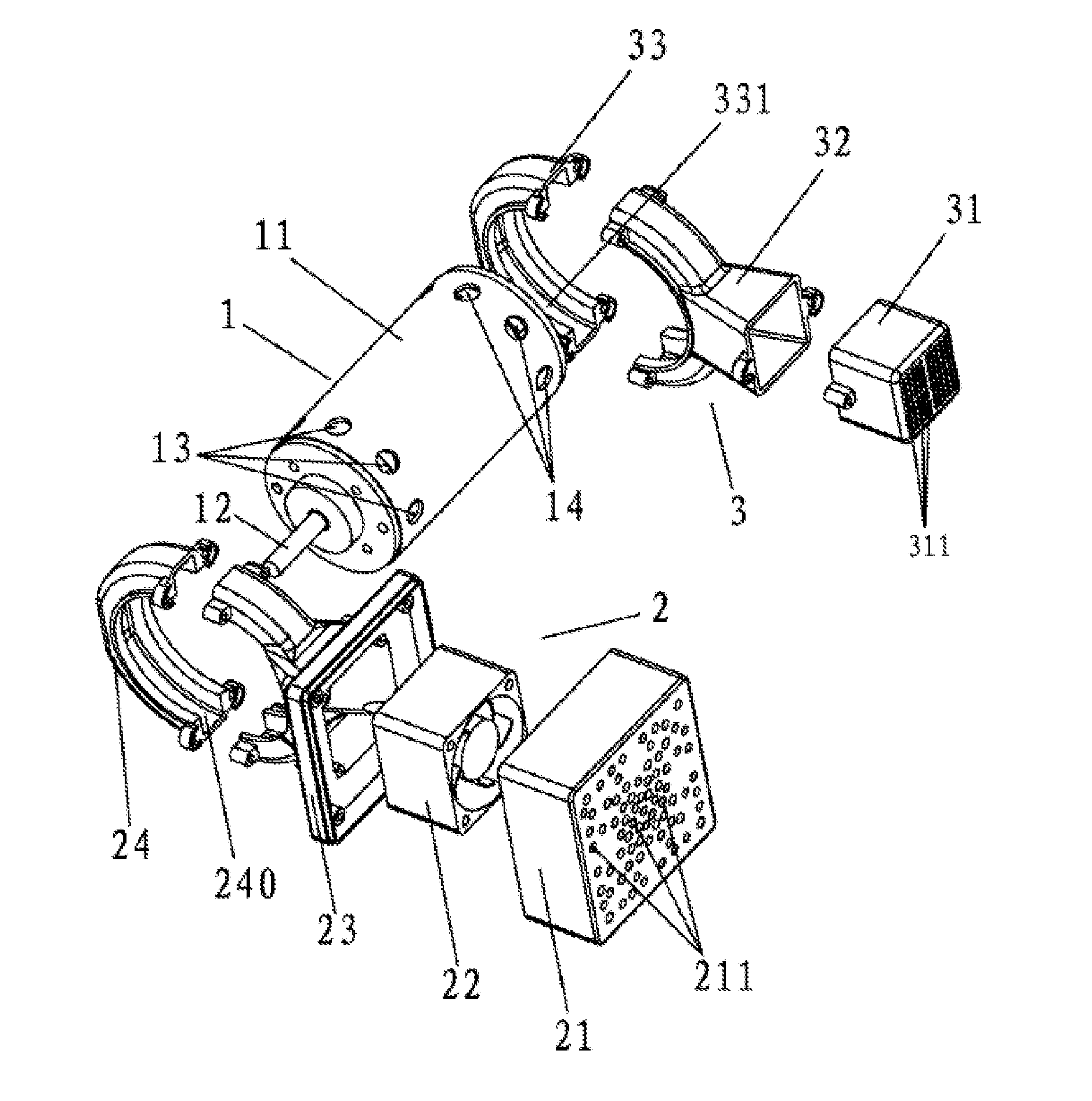
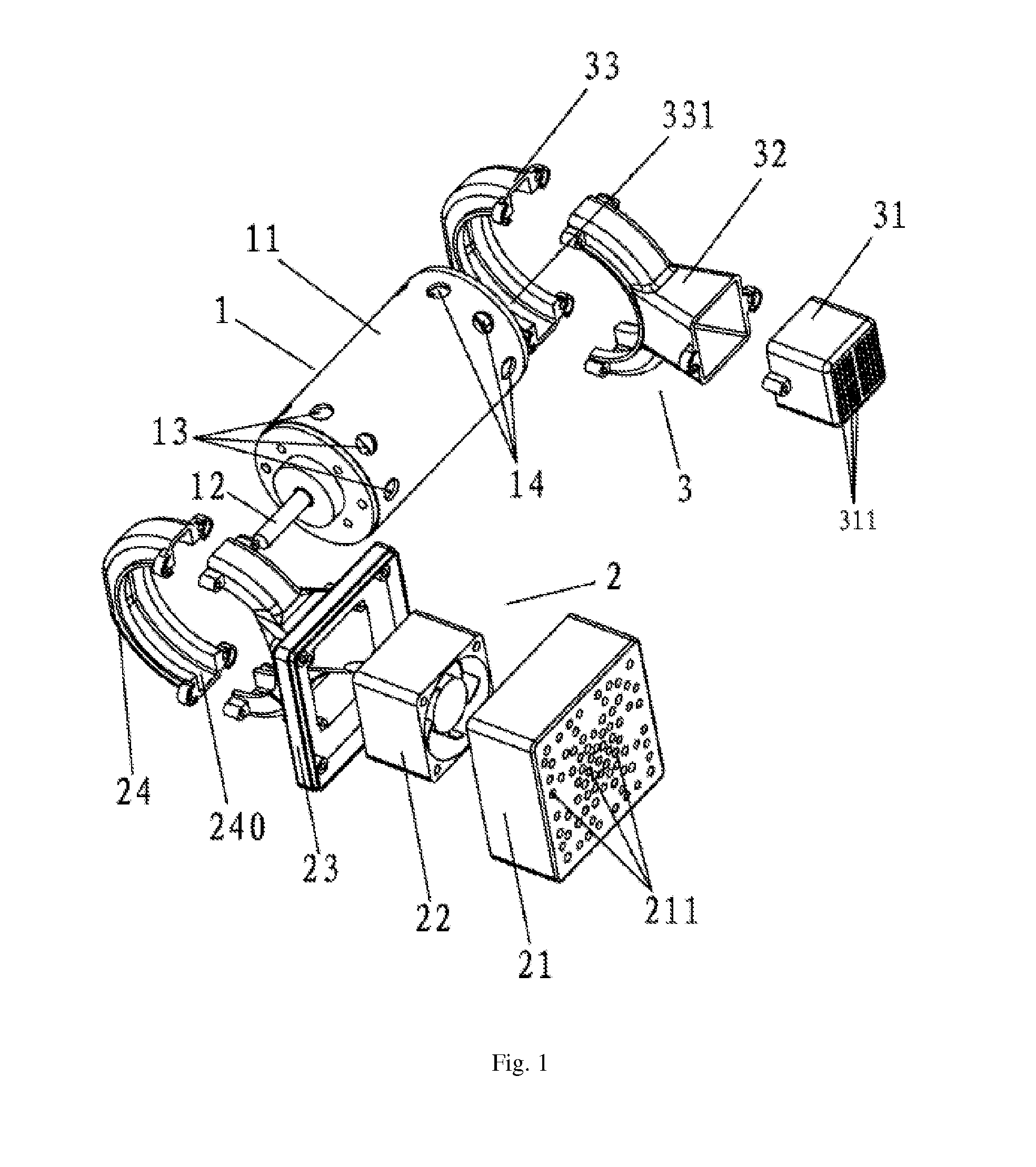
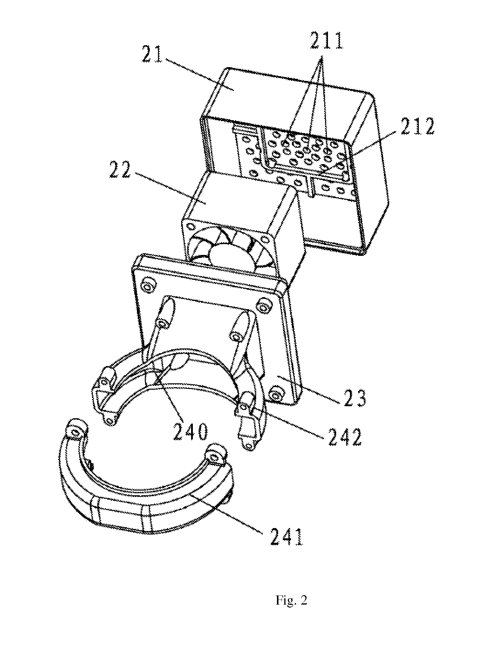
[0049]As shown in FIG. 1, the motor comprises a motor body 1, the motor body 1 is provided with an output shaft 12 and a motor housing body 11 that slips onto the output shaft 12, in which, the motor housing body 11 is provided with a heat dissipating device. The heat dissipating device comprises an air intake device 2 and an air output device 3. The air intake device 2 is mounted close to one side of the output shaft 12. The air output device 3 is mounted a distance from one side of the output shaft 12. The motor housing body 11 is provided with air inlet holes 13 on the position corresponding to the air intake device 2. The motor housing body 11 is also provided with air output holes 14 on the position corresponding to the air output device 3. The air intake device 2 is provided with a fan 22. The air inlet holes provided on the motor housing body 11 are arranged in a circular fashion, and the space between each of the air inlet hole 13 is equal. The air outp...

embodiment 2

Preferred Embodiment 2

[0061]As shown in FIG. 6, the paper shredder of the present invention comprises a housing 6 and a shredder head 4. The shredder head 4 is provided with a transmission mechanism 5 and a motor. The motor is similar to the one described in Preferred Embodiment 1, for which comprises a motor body. The motor body is provided with an output shaft that sleeves on the motor housing body 11. The motor housing body 11 is provided with a heat dissipating device. The heat dissipating device comprises an air intake device 2 and an air output device 3. The air intake device 2 is provided with cold air inlet holes 81. The air output device 3 is provided with hot air output holes 82. The air intake device 2 is mounted on one side of the output shaft. The air output device 3 is mounted on the other side of the output shaft. The motor housing body 11 is provided with air inlet holes on the position corresponding to the air intake device 2 and are connected through the cavity of ...

embodiment 3

Preferred Embodiment 3

[0063]As shown in FIGS. 8 and 9, the motor comprises a motor body 1. The motor body 1 is provided with an output shaft and a motor housing body 11 that sleeves onto the output shaft. The motor housing body 11 is provided with a heat dissipating device. The heat dissipating device comprises an air intake device 2 and an air output device 3. The air intake device 2 is mounted on one side of the output shaft; the air output device 3 is mounted on the other side of the output shaft. The air intake device 2 is provided with air inlet hole 13 (can also be used as cold air inlet hole). The air output device 3 is provided with hot air output hole 14. The air output device 3 is also provided with a axial fan 301. The axial fan 301 is mounted on the tail end of the motor housing body 11. The first end of the axial fan 301 is closed and the second end of the axial fan 301 is provided with air inlet holes 331 that parallel with the output shaft. The second end of the axial...


PUM


Abstract

Provided is a paper shredder comprising a housing (6) and a paper shredder head (4), wherein a transmission mechanism (5) and a motor are provided in the paper shredder head (4); the motor comprises a motor body (1), the motor body (1) having an output shaft (12) and a motor housing (11) sleeve connected on the output shaft (12); the motor housing (11) is provided with a heat dissipation device, the heat dissipation device comprising an air intake device (2) and an air output device (3); the air intake device (2) has a cold air inlet and the air output device (3) has a hot air outlet; the air intake device (2) is provided on one side of the output shaft (12) and the air output device (3) is provided on the other side of the output shaft (12); at the position where the air intake device (2) is provided on the motor housing (11) there is an air intake hole (13) opened correspondingly to communicate with an inner chamber of the motor housing (11), and at the position where the air output device (3) is provided on the motor housing (11) there is an air output hole (14) opened correspondingly to communicate with the inner chamber of the motor housing (11), such that a relatively isolated and independent heat dissipating air channel is formed internally from the cold air inlet, via the inner chamber of the motor housing (11), to the hot air outlet.

Description

BACKGROUND OF INVENTION[0001]1. Field of the Invention[0002]The present invention relates to a motorized paper shredder. The present invention is based on Chinese Utility Model Application No. 201020543836.3, filed on Sep. 27, 2010, and Chinese Utility Model Application No. 201120246575.3, filed on Jul. 13, 2011. The contents of the above-mentioned applications are incorporated herein by reference.[0003]2. Description of Related Art[0004]A motor, also called electric motor, is an energy conversion or transfer electromagnetic apparatus that functions according to the law of electromagnetic. It's main use to generate drive torque, thereby becoming the appliance or a power source of the various mechanical. Because motor operation is developed by solenoid cutting action, and the current resistance of the effect must produce heat, the greater the current, the more heat it generates. In continuous operation, the motor will accumulate a large amount of heat affecting the overall performanc...

Claims


Application Information

Patent Timeline
Patent Type & Authority Applications(United States)
IPC IPC(8): H02K9/04
CPCB02C18/0007B02C18/16H02K9/26H02K5/20H02K9/04B02C2018/0046H02K7/116H02K7/14H02K5/207
Inventor XU, NING
Owner DONGGUAN BONSEN ELECTRONICS
Why Eureka
Try Eureka