Control system for gantry truss robot and control method for control system for gantry truss robot

A truss robot and control system technology, applied in the direction of load hanging components, transportation and packaging, etc., can solve the problems of insufficient functional practicability and stability, unfavorable long-term use, singleness, etc., to improve stability and prolong service life , to avoid the effect of using wear

Active Publication Date: 2017-01-11
宁夏巨能机器人股份有限公司
View PDF6 Cites 1 Cited by
  • Summary
  • Abstract
  • Description
  • Claims
  • Application Information

AI Technical Summary

Problems solved by technology

[0007] At present, with the rapid development of the domestic manufacturing industry, with the rising labor costs of enterprises and the requirements of industrial transformation and upgrading, the improvement of equipment performance alone has very limited contribution to the improvement of productivity. Only the transformation of manufacturing mode and management mode can Let the productivity be improved by leaps and bounds, and the manufacturing mode integrating automation, flexibility and intelligence will be the general trend of the development of the manufacturing industry in the future. However, the control system for the gantry truss in the domestic market is relatively single and simple. Yes, there are deficiencies in the practicability and stability of the function, which is not conducive to long-term use

Method used


Image

  • Control system for gantry truss robot and control method for control system for gantry truss robot
  • Control system for gantry truss robot and control method for control system for gantry truss robot

Examples


Embodiment Construction

[0020] The following will clearly and completely describe the technical solutions in the embodiments of the present invention with reference to the accompanying drawings in the embodiments of the present invention. Obviously, the described embodiments are only some, not all, embodiments of the present invention.

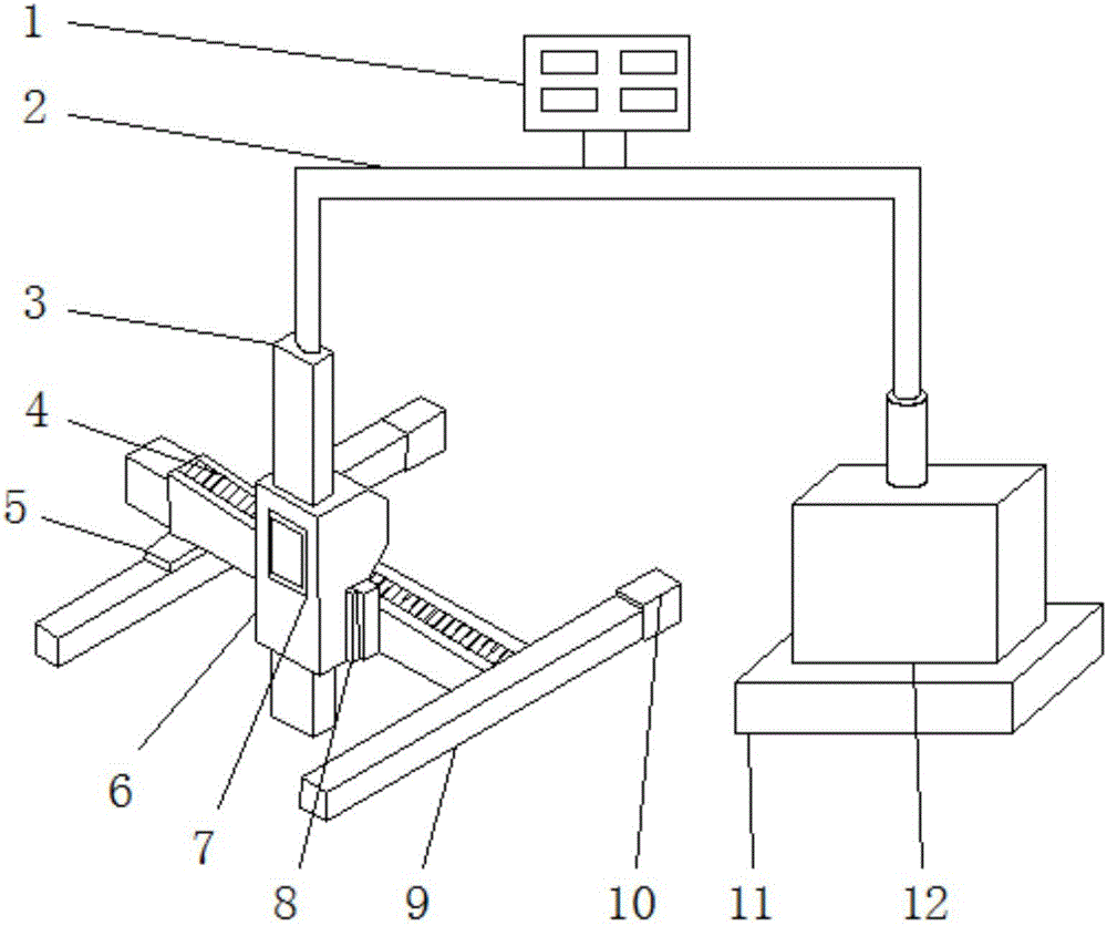
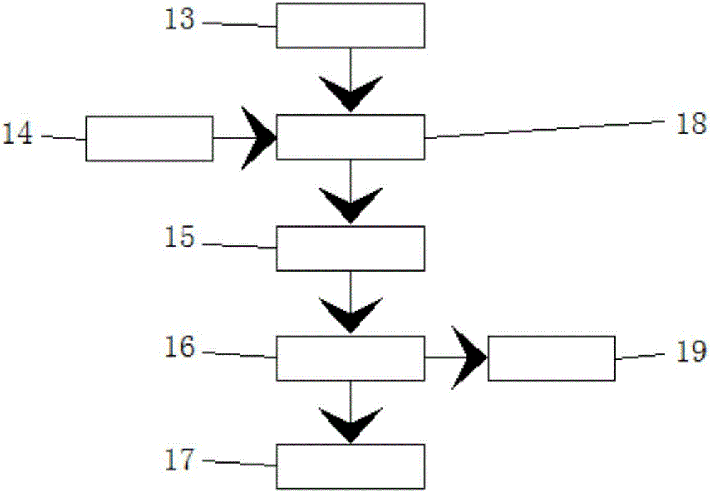
[0021] refer to Figure 1-2 , a control system for a gantry truss robot, comprising a body 6, an X-axis 9, an instruction processing module 16 and an instruction positioning module 18, a display screen 7 is installed on the front surface of the body 6, an X-axis 9 is installed on the right side of the body 6, and the X-axis 9 The Y axis 4 is installed on the right side, and the shaft spacer 5 is installed below the Y axis 4, the transmission device 8 is installed on the right surface of the body 6, the Z axis 3 is installed above the body 6, and the controller 1 is installed above the Z axis 3 A base 11 is installed on the right side of the X-axis 9, and a power devi...


PUM


Abstract

The invention discloses a control system for a gantry truss robot. The control system for the gantry truss robot comprises a machine body, an X shaft, a command processing module and a command positioning module. A display screen is mounted on the front surface of the machine body. The X shaft is mounted on the right side of the machine body. A Y shaft is mounted on the right side of the X shaft. A shaft spacer is mounted below the Y shaft. A Z shaft is mounted above the machine body. A controller is mounted above the Z shaft. The input end of the command positioning module is electrically connected with the output end of an initial command module and the output end of an external input module. The output end of the command positioning module is electrically connected with the input end of a command drive module. The output end of the command processing module is electrically connected with the input end of a command recovery module. The invention further provides a control method for the control system for the gantry truss robot. The mounted machine body is of a stainless steel corrosion-resisting structure, so that the machine body can be kept in the stable and safe operation state for a long time, meanwhile excessive use wear to the machine body is avoided, and thus the service life of the system is prolonged.

Description

technical field [0001] The invention relates to the technical field of gantry truss, in particular to a control system and a control method of a gantry truss robot. Background technique [0002] The gantry (mobile lifting small gantry) is a new type of small lifting gantry developed according to the daily production needs of medium and small factories (companies) for handling equipment, warehouse import and export, lifting and maintenance of heavy equipment and material transportation. It is suitable for making molds, auto repair factories, mines, civil construction sites and occasions that require lifting. [0003] It is commonly used in building construction as material transportation and construction personnel's upper and lower use to realize lifting mechanization. It can reduce manpower, reduce production and operation costs, and improve work efficiency. [0004] The biggest advantage of the mobile gantry is that it can be moved in all directions, can be disassembled a...

Claims


Application Information

Patent Timeline
Patent Type & Authority Applications(China)
IPC IPC(8): B66C13/22B66C13/00
CPCB66C13/00B66C13/22
Inventor 董德宋明安刘学平姬卫春高博麻辉
Owner 宁夏巨能机器人股份有限公司
Why Eureka
Try Eureka