Long-distance distributed optical fiber vibration monitoring device and realization method thereof

A distributed optical fiber and vibration monitoring technology, which is applied to measuring devices, measuring ultrasonic/sonic/infrasonic waves, instruments, etc., can solve the problems of high difficulty of zero point positioning algorithm, low hardware cost, poor positioning accuracy, etc., to improve optical signal transmission The effect of distance and signal analysis and recognition ability, application cost reduction, and economic benefit improvement

Inactive Publication Date: 2017-01-11
WEIHAI BEIYANG PHOTOELECTRIC INFORMATION TECH
View PDF4 Cites 2 Cited by
  • Summary
  • Abstract
  • Description
  • Claims
  • Application Information

AI Technical Summary

Problems solved by technology

Mach-Zehnder interferometer technology has a simple design structure, but it will be affected by polarization attenuation for long distances, resulting in extremely poor positioning accuracy and poor application effect; white light interferometry technology has low hardware cost, but the zero point positioning algorithm is difficult. At the same time, the problem of poor positioning accuracy will also exist due to the interference of the surrounding environment, which cannot meet the application; the phase-sensitive OTDR technology can accurately locate through the time domain, and there is no problem of positioning deviation. It has been successfully applied in pipeline safety monitoring.

Method used


Image

  • Long-distance distributed optical fiber vibration monitoring device and realization method thereof
  • Long-distance distributed optical fiber vibration monitoring device and realization method thereof
  • Long-distance distributed optical fiber vibration monitoring device and realization method thereof

Examples


Embodiment Construction

[0026] The specific implementation manners of the present invention will be described in detail below in conjunction with the technical solutions and accompanying drawings.

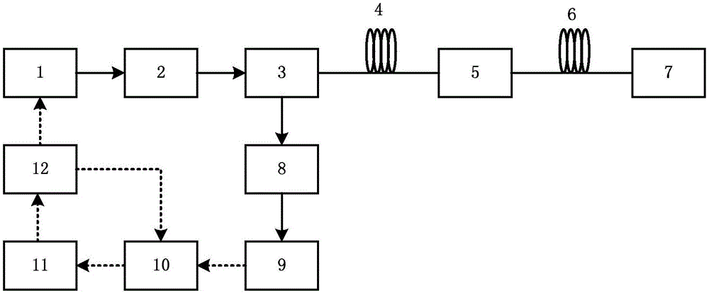
[0027] First, the pulse source (1) emits laser pulses, and the signal is amplified by the optical fiber amplifier (2) as a light source signal;

[0028] Second, the light source signal is delivered to the actual laying detection fiber 1 (4) through the 2 ports of the circulator (3), and each pulsed light arrival position in the fiber will generate a Rayleigh scattering signal, and the surrounding environmental vibration will is loaded into the Rayleigh scattering signal, causing its phase to change;

[0029] Third, after the light source reaches 25km in the detection fiber 1 (4), its energy decreases due to its attenuation, and the energy of its scattered signal is greatly reduced. After passing through the relay amplifier module (5), the light source and the amplified laser enter the detection fiber 2 ( ...


PUM


Abstract

The invention relates to the field of pipeline safety monitoring, and specifically relates to a long-distance distributed optical fiber vibration monitoring device employing optical fibers as sensors and a realization method thereof. The device is characterized in that the device comprises a pulse source, an optical fiber amplifier, a circulator, detection optical fibers, a relay amplification module, a backward amplification module, a narrowband filter, a signal detection module, an acquisition module, a synchronous control module, a host computer, a coupler, two wavelength division multiplexers, two amplification laser sources, two feedback detection modules, and power supply control modules. Compared with the prior art, according to the device, the monitoring distance of the system can be further extended, the application cost is obviously reduced, the economic benefit is substantially increased, the system design employs the optical time domain reflection positioning technology, the phase sensitive recognition technology, the distributed amplification technology, the remote signal control technology and the signal multi-resolution extraction technology, and the optical signal transmission distance and the signal analysis recognition capability are effectively increased.

Description

technical field [0001] The invention relates to the field of pipeline safety monitoring, in particular to a long-distance distributed optical fiber vibration monitoring device using optical fiber as a sensor and a realization method thereof. [0002] technical background [0003] With the development of optical fiber communication technology, optical fiber sensing technology is gradually emerging. The detection objects of optical fiber sensing are very wide, including temperature, humidity, strain, acceleration, vibration, voltage, current and other parameters. At the same time, it has the advantages of high sensitivity, good electrical insulation, anti-electromagnetic interference, and high measurement accuracy. application market. Distributed optical fiber sensing technology uses optical fiber not only as the sensing unit but also as the medium of signal transmission to realize the monitoring of all objects in the spatially distributed area of ​​optical fiber. In addition ...

Claims


Application Information

Patent Timeline
Patent Type & Authority Applications(China)
IPC IPC(8): G01H9/00
CPCG01H9/004
Inventor 纪圣华王建强张凯乔秋晓王秀亮
Owner WEIHAI BEIYANG PHOTOELECTRIC INFORMATION TECH
Why Eureka
Try Eureka