Rotating shaft system rotational inertia in-situ measurement device

A moment of inertia, in-situ measurement technology, applied in the direction of measuring device, static/dynamic balance test, machine/structural component test, etc., to achieve the effect of high measurement accuracy and compact structure

Active Publication Date: 2017-01-11
BEIJING CHANGCHENG INST OF METROLOGY & MEASUREMENT AVIATION IND CORP OF CHINA
View PDF8 Cites 7 Cited by
  • Summary
  • Abstract
  • Description
  • Claims
  • Application Information

AI Technical Summary

Problems solved by technology

[0003] At present, most of the calibration research on torque is focused on the static torque calibration research, and the measurement calibration of dynamic torque is still in the preliminary research stage.

Method used


Image

  • Rotating shaft system rotational inertia in-situ measurement device
  • Rotating shaft system rotational inertia in-situ measurement device
  • Rotating shaft system rotational inertia in-situ measurement device

Examples


Embodiment 1

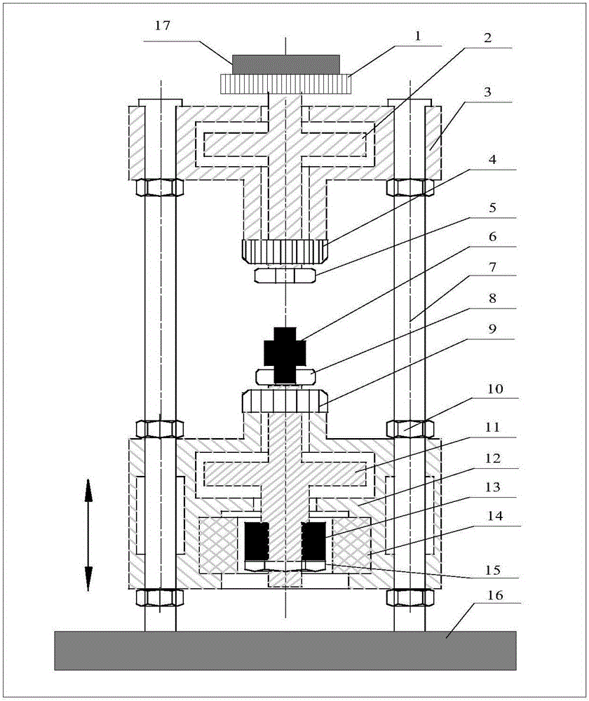
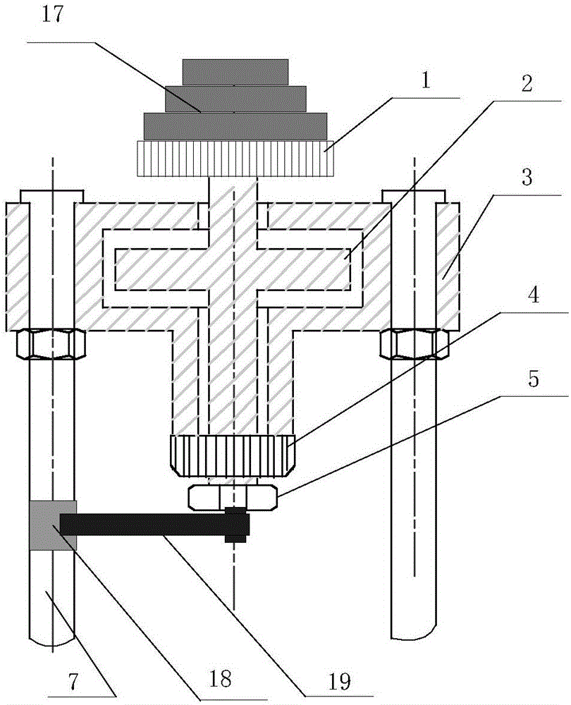
[0028] In-situ measuring device for the moment of inertia of the rotating shaft system, such as figure 2 As shown, it consists of an upper structure and a torsion system; the upper structure table top grating 1, the upper air bearing shaft 2, the upper bearing seat 3, the cylindrical grating 4, the upper interface 5 and the inertia standard block 17; the torsion system includes a fastening mechanism 18 and The torsion spring 19; the inertia standard block 17 is placed on the table top grating 1; the upper bearing seat 3 is an inverted convex structure with a through hole in the middle and a cavity inside; the cavity wall of the upper bearing seat 3 is provided with air passages and Air holes; the upper air bearing shaft 2 is a cross structure, and the upper air bearing shaft 2 is placed in the inner cavity of the upper bearing seat 3. When the cavity is filled with gas, the upper air bearing shaft 2 does not contact the upper bearing seat 3; the upper air bearing shaft 2 The ...

Embodiment 2

[0042] The structure of the in-situ measuring device for the moment of inertia of the rotating shaft system is the same as in Embodiment 1; the lower structure consists of the sensor to be calibrated 6, the lower interface 8, the feedback grating 9, the lower air bearing shaft 11, the lower bearing seat 12, the motor rotor 13, and the motor stator 14, composed of lock nut 15; the lower bearing seat 12 is a convex structure, with a through hole in the middle, and two upper and lower inner cavities inside; the lower air bearing shaft 11 is a cross structure, and the upper inner cavity of the lower bearing seat 12 is filled with The lower air bearing shaft 11 is not in contact with the lower bearing seat 12 when there is gas; the lower air bearing shaft 11 is placed in the upper inner cavity, the shaft passes through the through hole in the middle of the lower bearing seat 12, and the top end passes through the feedback grating 9 and is fixedly connected to the lower interface 8 T...


PUM


Abstract

The invention relates to a rotating shaft system rotational inertia in-situ measurement device. Standard rotational inertia blocks are installed at the top end of a shaft system, the given angle is generated by using a motor driving system and then released, and the shaft system is driven to freely vibrate by using a torsion spring; and the free vibration period is measured by a laser interferometer, testing is performed by using more than two standard rotational inertia blocks, and the no-load rotational inertia of the shaft system can be obtained through calculation. The mechanical structure of a dynamic torque calibration system and a measurement system are utilized, and in-situ measurement of the no-load shaft system rotational inertia can be realized by increasing one torsion spring and electromagnetic clutch so that the structure is compact and the measurement accuracy is high.

Description

technical field [0001] The invention relates to an in-situ measuring device for the moment of inertia of a rotating shaft system, in particular to an in-situ measuring device for the moment of inertia of a rotating shaft system in a dynamic torque calibration device, and belongs to the field of metrology and testing. Background technique [0002] Aviation, aerospace, ships, armored vehicles, marine engineering, material science, anti-terrorist robots and other fields use dynamic torque test systems extensively. However, the above-mentioned equipment cannot be dynamically calibrated and is in the stage of "static standard use". Due to the inconsistency of calibration and use status, the uncertainty of its use is greatly increased. [0003] At present, most of the calibration researches on torque focus on static torque calibration research, and the measurement calibration of dynamic torque is still in the preliminary research stage. There are generally two types of excitation...

Claims


Application Information

Patent Timeline
Patent Type & Authority Applications(China)
IPC IPC(8): G01M1/10
CPCG01M1/10
Inventor 张力彭军尹肖
Owner BEIJING CHANGCHENG INST OF METROLOGY & MEASUREMENT AVIATION IND CORP OF CHINA
Why Eureka
Try Eureka