Eureka AIR delivers breakthrough ideas for toughest innovation challenges, trusted by R&D personnel around the world.

Display module visible in sunlight

A display module and sunlight technology, applied in optics, nonlinear optics, instruments, etc., can solve problems such as unsatisfactory anti-reflection effects, achieve excellent visual effects, ensure transmittance, and improve anti-reflection effects

Pending Publication Date: 2017-01-11
SHANGHAI GUANXIAN OPTOELECTRONICS TECH CO LTD
View PDF10 Cites 5 Cited by
  • Summary
  • Abstract
  • Description
  • Claims
  • Application Information

AI Technical Summary

Problems solved by technology

In addition, the full lamination technology can also be used as an auxiliary means to reduce reflection. Although the existing technology can reduce reflection to a certain extent and improve the visibility under sunlight, it is limited by the wavelength selectivity of the anti-reflection film and the refractive index of the glue. It cannot accurately match the minimum reflection conditions, and its anti-reflection effect is not ideal. Usually, the reflectivity can only be controlled at 1-2%, and it is difficult to achieve within 1%. Usually, the effective contrast ratio (ECR, ECR=1+display brightness / Reflected light brightness), this parameter represents the strength of readability under sunlight, the higher the ECR, the better the readability under strong light, at least ensure that ECR>5 will have better visibility under sunlight

Method used


Image

  • Display module visible in sunlight
  • Display module visible in sunlight
  • Display module visible in sunlight

Examples


Embodiment 1

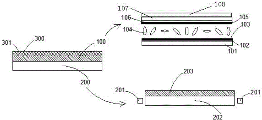
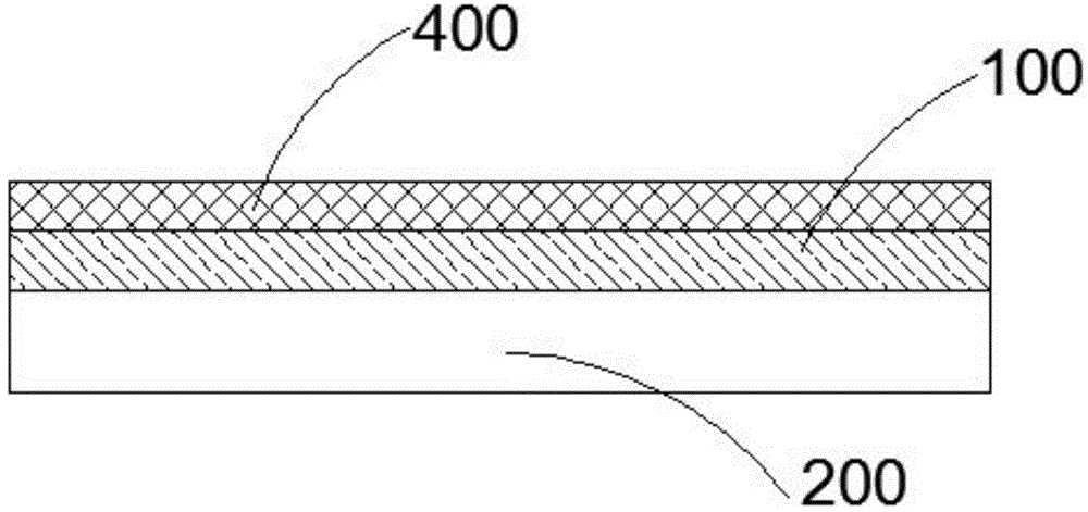
[0039] Such as figure 2 Shown is a cross-sectional view of a display module visible under sunlight according to the present invention. figure 2 Among them, from bottom to top are the backlight module 200, the display screen 100, and the circular polarizer layer 400. By adding the circular polarizer layer 400 to the existing display module structure, the circular polarizer layer 400 has the characteristic of reducing reflected light, mainly By reflecting and shielding the light incident in the liquid crystal display module, the reflected light can be further reduced. The present invention can further reduce the reflectance to less than 1%, and ensure ECR>5 to obtain excellent visibility under sunlight, thereby The display module has an excellent visual effect under sunlight. In this embodiment, if a display module visible under sunlight is not equipped with the touch module 300, the display module has less touch Control function, but it also has a visible effect under sunlig...

Embodiment 2

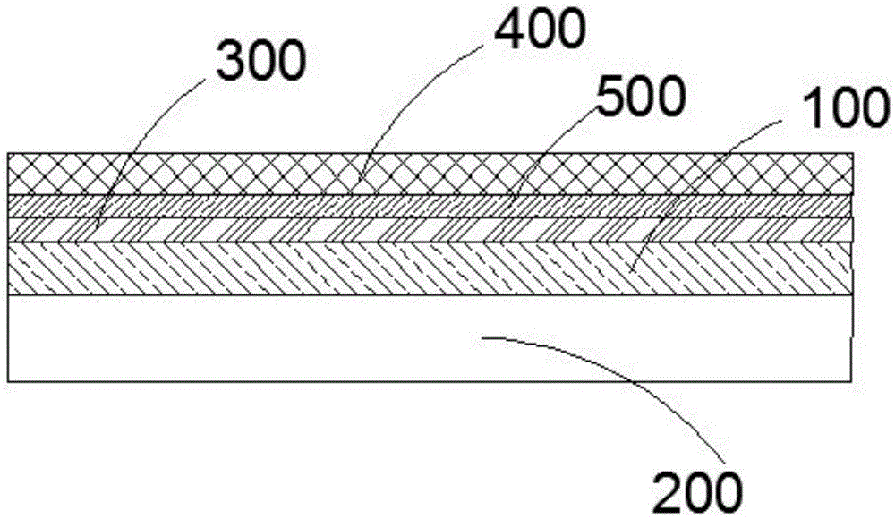
[0041] Such as Figure 5 Shown is a cross-sectional view of a display module visible under sunlight according to the present invention, which Figure 5 Among them, from bottom to top are, respectively, the backlight module 200, the display screen 100, the wave plate layer 500, the touch module 300, and the circular polarizer layer 400. In this embodiment, the light transmission axis of the polarizer layer 108 on the display screen 100 0°. Circular polarizer layer 400 adopts a combined structure of linear polarizer + quarter-wave plate. The surface of one side of the linear polarizer in circular polarizer layer 400 is coated with an anti-reflection film. The angle between the light transmission axes of the sheets 108 is 45°. The wave plate layer 500 adopts a quarter wave plate layer, and the angle between the optical axis and the light transmission axis of the polarizer layer 108 on the display screen 100 is 45° (see FIG. 6 ), Figure 6a It shows the principle of light path ...

Embodiment 3

[0043] Such as Figure 7 Shown is a cross-sectional view of another sunlight-visible display module provided by the present invention, which includes a backlight module 200, a display screen 100, a wave plate layer 500, a circular polarizer layer 400, and a touch screen from bottom to top. Control module 300. In this embodiment, the light transmission axis of the polarizer layer 108 on the display screen 100 is 0°. The circular polarizer adopts a combined structure of a linear polarizer + a quarter-wave plate, one side of the circular polarizer linear polarizer is coated with an anti-reflection film, and the transmission axis of the linear polarizer is 45°, which is transparent to the polarizer layer 108 on the display screen 100. The included angle of the optical axis is 45°. The wave plate layer 500 adopts a quarter wave plate, and the angle between the optical axis and the transmission axis of the polarizer layer 108 on the display screen 100 is 45° (see FIG. 6 ). The pr...


PUM

PropertyMeasurementUnit
refractive indexaaaaaaaaaa

Abstract

The invention provides a display module visible in the sunlight. The display module comprises a display screen and a backlight module. The display screen comprises a first substrate and a second substrate, between which a liquid crystal material layer is arranged. Substrate film layers are arranged among the first substrate, the second substrate and the liquid crystal material layer. The display module further comprises a circular polarized layer. The display layer is arranged between the circular polarized layer and the backlight module. The display module visible in the sunlight has following beneficial effects: by adding the circular polarized layer and a wave-plate layer in the structure of the display module, a circular polarizer has the feature of antireflection; the feature is fulfilled by reflecting and shielding light into the liquid crystal display module so that antireflection is achieved; when the circular polarizer is adopted, light emitted according to the Malus law is subjected to brightness decay and brightness of emergent light is improved by increasing wave-plate layers; and the display module has the best effect of being visible in the sunlight.

Description

technical field [0001] The invention relates to a liquid crystal display module, in particular to a display module visible under sunlight. Background technique [0002] Outdoor display devices all have the requirement of being visible under sunlight. These devices include handheld mobile terminal products, such as mobile phones, GPS, POS machines, code scanners, outdoor advertising machines, ATM machines, and industrial computer products, covering a wide range of products. The existing mainstream display technology is mainly liquid crystal display technology (divided into active type and passive type, active type is subdivided by TFT material including amorphous silicon (a-Si), low temperature polysilicon (LTPS), oxide semiconductor (Oxide)), organic Light-emitting (OLED) display technology, quantum dot (Qdot) display technology. At present, LCD technology still occupies an absolute dominant position. After years of development, liquid crystal display technology has conti...

Claims


Application Information

Patent Timeline
Patent Type & Authority Applications(China)
IPC IPC(8): G02F1/1335
CPCG02F1/133514G02F1/133528
Inventor 邢亮尚有魁
Owner SHANGHAI GUANXIAN OPTOELECTRONICS TECH CO LTD
Why Eureka
Eureka Blog
Learn More