Wheel hub mounting hole flexible and automatic machining system based on machine vision

An automatic processing and machine vision technology, applied in general control systems, control/adjustment systems, instruments, etc., can solve problems such as the limitation of artificial wheel hub processing efficiency

Active Publication Date: 2017-01-11
中科图灵视控(北京)智能科技有限公司
View PDF7 Cites 19 Cited by
  • Summary
  • Abstract
  • Description
  • Claims
  • Application Information

AI Technical Summary

Problems solved by technology

[0004] In order to solve the above-mentioned problems that the processing of the existing wheel hub mounting holes requires manual adjustment of related processing equipment according to production requirements and the limitation of wheel hub processing efficiency, the present invention provides a flexible automatic processing system for wheel hub mounting holes based on machine vision. The specific scheme is as follows:

Method used


Image

  • Wheel hub mounting hole flexible and automatic machining system based on machine vision
  • Wheel hub mounting hole flexible and automatic machining system based on machine vision
  • Wheel hub mounting hole flexible and automatic machining system based on machine vision

Examples


Embodiment 1

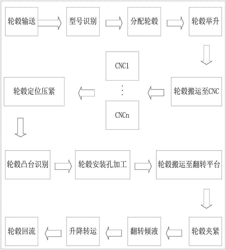
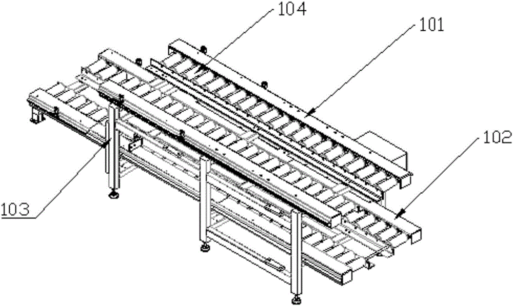
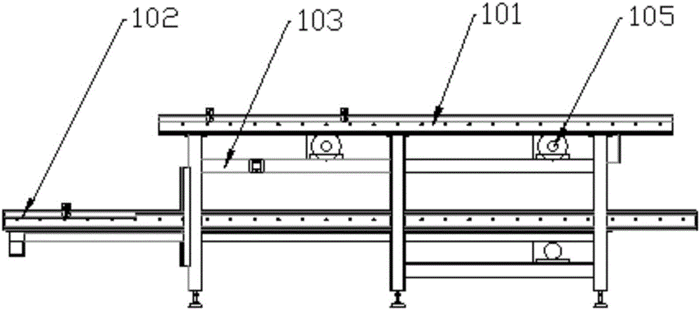
[0033] see Figure 1-7 As shown, the present invention provides a flexible automatic processing system for hub mounting holes based on machine vision, including a conveying system 1, an automatic loading and unloading system 5, a processing system 7, a positioning system 3, a vision system and a pouring and returning system 4; the conveying system 1 is an upper and lower two-layer structure fixed on the conveyor frame 103, the upper layer structure is the feeding layer 101, and the lower layer structure is the return layer 102, and the feeding layer 101 and the return layer 102 include several feeding rollers arranged on the conveyor frame 103 104, the two ends of feeding drum 104 are all provided with some sprockets, and the conveyer frame 103 is also provided with the driving motor 105 that is connected with chain wheels by chain; Moreover, the reflow layer 102 passes under the loading and unloading guide rail 502 and corresponds to the position of the pouring backflow syste...

Embodiment 2

[0041] see Figure 8-10 As shown, the difference between embodiment 2 and embodiment 1 is:

[0042] The automatic loading and unloading system 5 includes a first loading and unloading guide rail 511 and two second loading and unloading guide rails 512 arranged on the loading and unloading frame, and a first clamping device 503 arranged on the first loading and unloading guide rail 511 through a connecting plate, The second loading and unloading guide rail 512 and the first loading and unloading guide rail 511 form an "H"-shaped structure, and the processing system 7 is four CNC numerical control processing machine tools, which are distributed on both sides of the automatic loading and unloading system 5 .


PUM


Abstract

The invention discloses a wheel hub mounting hole flexible and automatic machining system based on machine vision, comprising a conveying system, an automatic feeding and discharging system, a machining system, a positioning system, a vision system, a poured liquid return system, and a computer control system. A model identification system is used to identify a to-be-machined wheel hub on a feeding layer and compare the model of the to-be-machined wheel hub with models pre-stored in a computer system, the corresponding machining system is allocated for the to-be-machined wheel hub according to the comparison result, the to-be-machined wheel hub is transferred to the allocated machining system by the automatic feeding and discharging system, and the to-be-machined wheel hub is clamped and positioned by the positioning system; then, a machining identification system shoots a static image of the wheel hub through an industrial camera and a light source and analyzes and processes the image, and the circumferential coordinate location of the boss of the wheel hub is calculated to provide a machining location coordinate for a CNC numerical control machine tool to machine the wheel hub; and finally, cuttings and cutting fluid on the surface of the machined wheel hub are cleaned by the poured liquid return system, and the wheel hub is conveyed to a specified location through a return layer.

Description

technical field [0001] The present invention relates to a mechanical processing equipment, and further relates to a wheel hub mounting hole processing system, in particular to a machine vision-based flexible automatic processing system for wheel hub mounting holes. Background technique [0002] The wheel hub is also called the rim, the wheel, and the tire bell. It is a barrel-shaped, center-mounted metal part that supports the tire on the inner profile of the tire. There are many types of hubs according to diameter, width, molding method and material. There are three methods of manufacturing aluminum alloy wheels: gravity casting, forging, and low-pressure precision casting. The gravity casting method uses gravity to pour the aluminum alloy solution into the mold, and after forming, it is processed and polished by a lathe to complete the production; the manufacturing process is relatively simple, does not require precision casting technology, the cost is low and the product...

Claims


Application Information

Patent Timeline
Patent Type & Authority Applications(China)
IPC IPC(8): G05B19/401G05B19/19
CPCG05B19/19G05B19/401
Inventor 江惟上陈庆文李健雅周凯
Owner 中科图灵视控(北京)智能科技有限公司
Why Eureka
Try Eureka