
Anti-icing starter solenoid switch with double-layer static contacts

An electromagnetic switch, anti-icing technology, applied in electromagnetic relays, electromagnetic relay details, circuits, etc., can solve the problems of electromagnetic switches that cannot conduct circuits, cannot reliably prevent icing, and high costs, and achieves solutions to contact junctions. Ice problem, safe and reliable use, long service life

Active Publication Date: 2018-06-29
JINZHOU HALLA ELECTRICAL EQUIP
View PDF6 Cites 0 Cited by
  • Summary
  • Abstract
  • Description
  • Claims
  • Application Information

AI Technical Summary

Problems solved by technology

When the electromagnetic coil is charged, the moving iron core moves down, thereby driving the moving contact rod and the moving contact piece to move down, so that the two ends of the moving contact piece are respectively connected with the two static contacts to conduct current, but there are the following problems: when the electromagnetic The temperature outside the switch drops, and the heat begins to lose from the switch casing. The material of the two T-bolts as the static contact is metal, so the heat loss is faster than the surrounding plastic static contact seat, and the temperature is earlier than other When the component drops below 0°C, the water vapor inside the switch will first condense into ice on the contact area of ​​the two static contact surfaces, and the electromagnetic switch with frozen contacts cannot conduct the circuit, and the starter cannot start normally
However, the two sets of contact mechanisms introduce new problems: complex structure, high cost, and large volume
However, this solution also has shortcomings: because the helical spring contact has an ablation every time the switch is turned on, the upper end of the spring is almost the same as the height of the static contact after multiple ablation consumptions. Unreliable protection against icing at end of life

Method used


Image

  • Anti-icing starter solenoid switch with double-layer static contacts
  • Anti-icing starter solenoid switch with double-layer static contacts
  • Anti-icing starter solenoid switch with double-layer static contacts

Examples


Embodiment Construction

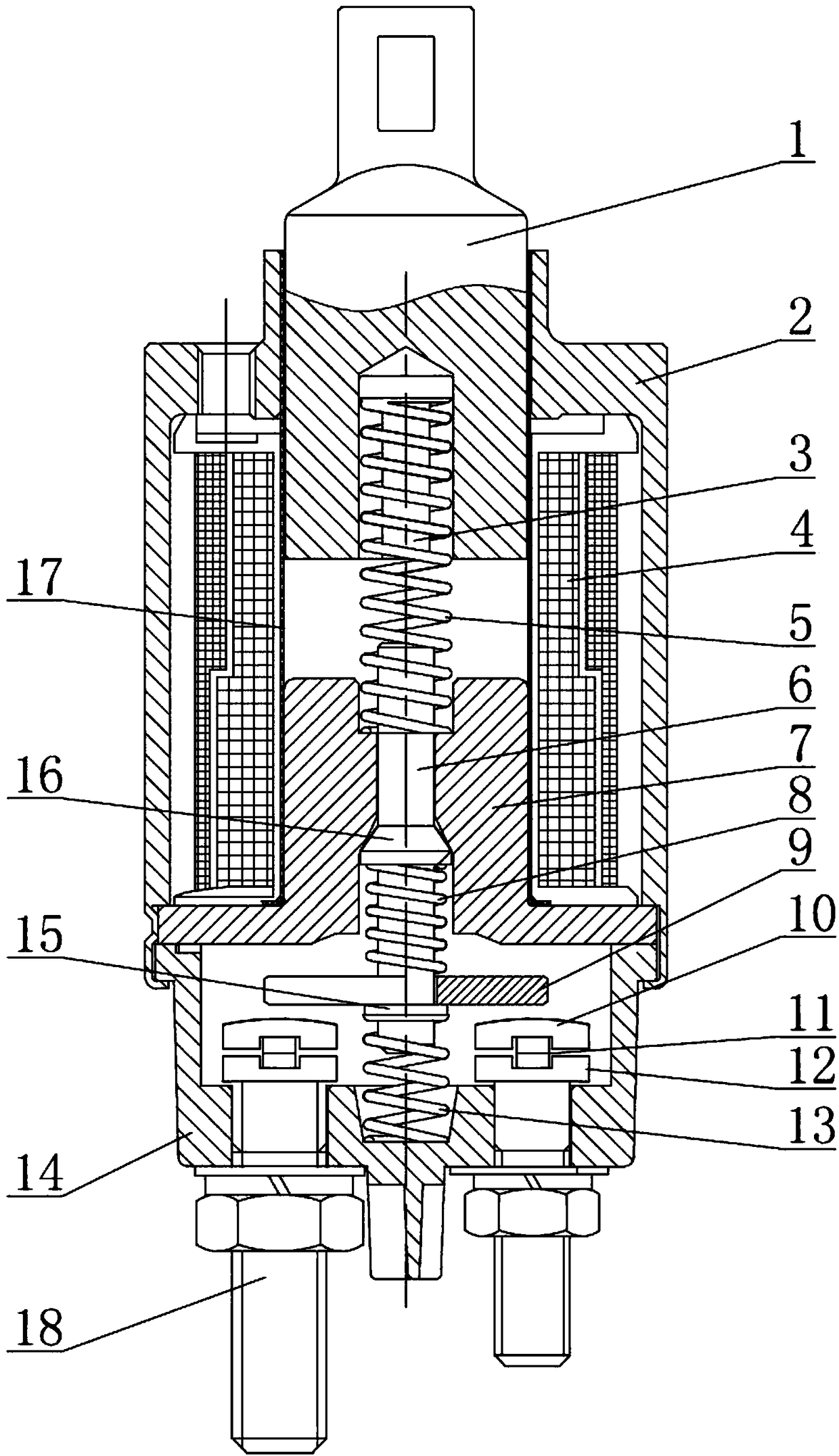
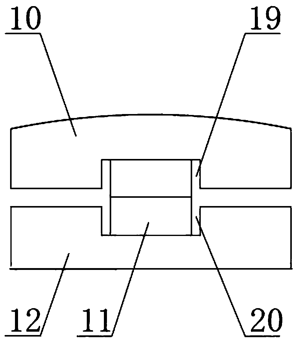
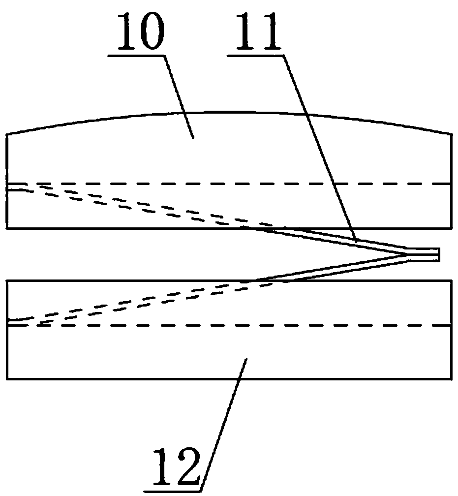
[0017] Such as Figure 1-Figure 3 As shown, the anti-icing starter electromagnetic switch with double-layer static contacts includes a housing 2, a static contact seat 14 located at the bottom of the housing 2, two static contacts located in the static contact seat 14, a fixed The ring-shaped support limit seat 7 above the static contact seat 14, the movable contact rod 6 set in the center of the ring-shaped support limit seat 7, the movable contact rod 6 arranged at the lower end of the movable contact rod 6 and perpendicular to the movable contact rod 6 Sheet 9, the reset spring 13 set between the lower end of the moving contact rod 6 and the bottom surface of the static contact seat 14, the sleeve 17 set on the upper periphery of the annular support limit seat 7, and the sleeve 17 formed by the shell 2 The electromagnetic coil 4 in the annular space, the moving iron core 1 that is located on the top of the annular support limit seat 7 and can slide along the inner wall of t...


PUM


Abstract

The present invention relates to an anti-freeze starter electromagnetic switch with a double-layer stationary contact, and the electromagnetic switch is characterized in that the central part of a movable contact piece is provided with a through hole; the lower end of a movable contact rod passes through the through hole of the movable contact piece, and a clamp spring is employed for limiting, so as to prevent the movable contact piece from being separated from the movable contact rod; the movable contact rod between an annular stopper boss and the movable contact piece is provided with a compression spring in a sleeved manner; The stationary contact consists of a screw rod and a double-layer stationary contact piece structure disposed at the top of the screw rod; the double-layer stationary contact piece structure consists of a lower stationary contact piece, an upper stationary contact piece and a spring piece between the lower stationary contact piece and the upper stationary contact piece; the spring piece is made of a bimetallic sheet which is deformed with temperature. The electromagnetic switch solves a problem of contact freezing fundamentally, is simple in structure, is low in cost, is small in size, is long in service life, is reliable for use, and is wide in application range.

Description

technical field [0001] The invention relates to a starter electromagnetic switch for vehicles, in particular to an anti-icing starter electromagnetic switch with double-layer static contacts. Background technique [0002] The traditional starter electromagnetic switch consists of a housing, a static contact seat located at the bottom of the housing, two static contacts located in the static contact seat, a ring support limit seat fixed above the static contact seat, and a ring support The moving contact rod in the center of the limit seat, the moving contact sheet fixed on the lower end of the moving contact rod and perpendicular to the moving contact rod, the return spring arranged between the lower end of the moving contact rod and the bottom surface of the static contact seat, is set on The sleeve on the outer periphery of the upper part of the annular support limit seat, the electromagnetic coil arranged in the annular space formed by the sleeve and the casing, the movin...

Claims


Application Information

Patent Timeline
Patent Type & Authority Patents(China)
IPC IPC(8): H01H50/54H01H50/12H01H51/06
CPCH01H50/12H01H50/54H01H51/065
Inventor 吴日龙陈鹏任琛
Owner JINZHOU HALLA ELECTRICAL EQUIP
Learn More