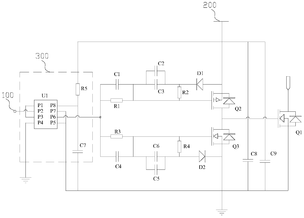
A drive circuit for a mos tube

A technology of MOS tube and drive circuit, which is applied in the field of switching circuit drive, can solve the problems of insufficient drive of MOS tube, drive drop drive signal, increase of volume and cost, etc., and achieve the effect of improving drive reliability, reducing loss and improving efficiency

Active Publication Date: 2019-09-10
SICHUAN SHENGHUA POWER TECH CO LTD
View PDF5 Cites 0 Cited by
  • Summary
  • Abstract
  • Description
  • Claims
  • Application Information

AI Technical Summary

Problems solved by technology

[0002] According to the current metal-oxide-semiconductor field effect transistor (MOSFET) drive scheme, especially in high-voltage applications, when driving a MOS tube with a large Miller capacitance, it is easy to cause a drive drop (There is a glitch in the drive signal), and the phenomenon of insufficient drive to the MOS tube
Therefore, an auxiliary source or amplifier must be added to provide a strong level signal, but this increases the size and cost, and it is also easy to cause driving delays, resulting in power loss

Method used


Image

  • A drive circuit for a mos tube

Examples


Embodiment Construction

[0020] In order to make the purpose, technical solutions and advantages of the embodiments of the present invention clearer, the technical solutions in the embodiments of the present invention will be clearly and completely described below in conjunction with the drawings in the embodiments of the present invention. Obviously, the described embodiments It is a part of embodiments of the present invention, but not all embodiments. The components of the embodiments of the invention generally described and illustrated in the figures herein may be arranged and designed in a variety of different configurations.

[0021] Accordingly, the following detailed description of the embodiments of the invention provided in the accompanying drawings is not intended to limit the scope of the claimed invention, but merely represents selected embodiments of the invention. Based on the embodiments of the present invention, all other embodiments obtained by persons of ordinary skill in the art wi...


PUM


Abstract

The embodiment of the invention provides an MOS (Metal Oxide Semiconductor) transistor driving circuit. The MOS transistor driving circuit provided by the embodiment of the invention is used for driving a main MOS transistor, and comprises a signal input end, a first branch and a second branch, wherein the first branch and the second branch are connected in parallel and are connected between the signal input end and the main MOS transistor, and the first branch is further connected to a power supply. Through a voltage dividing network provided with the first branch and the second branch, effective control for driving is realized, the driving capacity is improved, and a driving problem caused by existence of intrinsic Miller capacitance of a high-voltage MOS transistor is solved. The driving capacity is improved, so that the loss of the main MOS transistor is reduced, and the efficiency is improved. Meanwhile, direct connection of a P-channel MOS transistor and an N-channel MOS transistor is avoided because of existence of charging and discharging time constants of capacitance of the voltage dividing network provided with the first branch and the second branch, and the driving reliability is greatly improved.

Description

technical field [0001] The invention relates to the technical field of switch circuit drive, in particular, to a drive circuit of a MOS transistor. Background technique [0002] According to the current metal-oxide-semiconductor field effect transistor (MOSFET) drive scheme, especially in high-voltage applications, when driving a MOS tube with a large Miller capacitance, it is easy to cause a drive drop (There is a glitch in the driving signal), and the phenomenon of insufficient driving of the MOS tube. Therefore, an auxiliary source or amplifier must be added to provide a strong level signal, but this increases the size and cost, and it is easy to cause driving delay and cause power loss. Contents of the invention [0003] In view of this, the purpose of the embodiments of the present invention is to provide a driving circuit for a MOS transistor, so as to improve the problem of insufficient driving of a MOS transistor with a large Miller capacitance in the prior art. ...

Claims


Application Information

Patent Timeline
Patent Type & Authority Patents(China)
IPC IPC(8): H03K17/687H03K17/689
Inventor 冯骏范永明孔君
Owner SICHUAN SHENGHUA POWER TECH CO LTD
Why Eureka
Try Eureka