Flash lamp driving circuit

A technology for driving circuits and flashlights, applied in the field of communication, can solve the problems of wasteful circuit design, low efficiency, consumption, etc., and achieve the effect of improving driving efficiency and reducing voltage loss

Inactive Publication Date: 2017-01-11
SHENZHEN TINNO WIRELESS TECH
View PDF10 Cites 7 Cited by
  • Summary
  • Abstract
  • Description
  • Claims
  • Application Information

AI Technical Summary

Problems solved by technology

This power supply method causes a large part of the voltage drop to be consumed inside the flash driver, and the e

Method used


Image

  • Flash lamp driving circuit

Examples


Example Embodiment

[0017] The technical solutions in the embodiments of the present invention will be clearly and completely described below in conjunction with the accompanying drawings in the embodiments of the present invention. Obviously, the described embodiments are only a part of the embodiments of the present invention, not all the embodiments. Based on the embodiments of the present invention, all other embodiments obtained by those of ordinary skill in the art without creative work shall fall within the protection scope of the present invention.
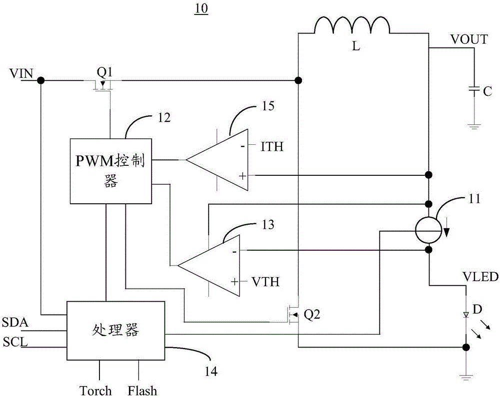
[0018] figure 1 It is a schematic diagram of the structure of the flash drive circuit of the embodiment of the present invention. Such as figure 1 As shown, the flash drive circuit 10 includes: a first MOS tube Q1, a second MOS tube Q2, an inductor L, a capacitor C, a constant current source 11, and a PWM controller 12. The gate of the first MOS transistor Q1 is connected to the PWM controller 12, the drain is connected to the input voltage, t...


PUM


Abstract

The invention discloses a flash lamp driving circuit. The flash lamp driving circuit comprises a first MOS transistor, a second MOS transistor, an inductor, a capacitor, a constant current source and a PWM controller, wherein the gate of the first MOS transistor is connected with the PWM controller, the drain of the first MOS transistor is connected to an input voltage, and the source of the first MOS transistor is connected with one end of the inductor; the other end of the inductor is grounded through the capacitor; the constant current source is connected between the other end of the inductor and the positive electrode of the flash lamp; the negative electrode of the flash lamp is grounded; the gate of the second MOS transistor is connected with the PWM controller, the drain of the second MOS transistor is connected with one end of the inductor, and the source of the second MOS transistor is grounded; and the PWM controller is used for controlling the on and off of the first MOS transistor and the second MOS transistor to further control a flash mode of the flash lamp circuit. By adoption of the mode, the constant current source is added to control the current of the flash lamp, so that voltage loss can be reduced while the driving efficiency of the flash lamp can be improved.

Description

technical field [0001] The invention relates to the technical field of communication, in particular to a flashlight driving circuit. Background technique [0002] The working voltage of the current mobile phone is generally 3.2 ~ 4.5V, and the working voltage of the flashlight is generally lower than 3.2V. The flash drive mostly adopts a switching DC boost (Boost) architecture, so it is generally not necessary to start the Boost boost circuit within the working voltage range of the mobile phone. The flash driver usually works in the bypass (Bypass) mode, that is, the flash is directly powered by the battery of the mobile phone. This power supply method causes a large part of the voltage drop to be consumed inside the flash driver, which has low efficiency. In addition, the Boost architecture will basically not work, which is a waste of circuit design. Contents of the invention [0003] The embodiment of the present invention provides a flash lamp driving circuit, which a...

Claims


Application Information

Patent Timeline
IPC IPC(8): H05B37/02
CPCH05B47/10
Inventor 李新倪漫利王晨
Owner SHENZHEN TINNO WIRELESS TECH
Why Eureka
Try Eureka