A photoelectric sensor, its control method, and pulse detector

A photoelectric sensor and pulse signal technology, which is applied in the direction of optical sensors, sensors, diagnostic recording/measurement, etc., can solve the problems of pulse wave influence, distortion, and reduce the accuracy of the pulse signal of photoelectric sensors

Active Publication Date: 2017-12-08
BOE TECH GRP CO LTD
View PDF5 Cites 0 Cited by
  • Summary
  • Abstract
  • Description
  • Claims
  • Application Information

AI Technical Summary

Problems solved by technology

[0004] However, in the process of using the photoelectric sensor to test the pulse, because the swing of the arm will cause motion interference to the photoelectric sensor, the motion interference will affect the pulse wave
like figure 2 As shown, the photoelectric sensor is disturbed by motion at time t1, which makes the amplitude of the pulse wave increase abnormally; the motion interference disappears at time t2, and the pulse wave returns to normal; figure 1 and figure 2 Comparing the waveforms of the test results, it can be seen that the pulse waveform is distorted due to motion interference, which in turn reduces the accuracy of the pulse signal detected by the photoelectric sensor.

Method used


Image

  • A photoelectric sensor, its control method, and pulse detector
  • A photoelectric sensor, its control method, and pulse detector
  • A photoelectric sensor, its control method, and pulse detector

Examples


Embodiment Construction

[0039] The following will clearly and completely describe the technical solutions in the embodiments of the present invention with reference to the accompanying drawings in the embodiments of the present invention. Obviously, the described embodiments are only some, not all, embodiments of the present invention. Based on the embodiments of the present invention, all other embodiments obtained by persons of ordinary skill in the art without making creative efforts belong to the protection scope of the present invention.

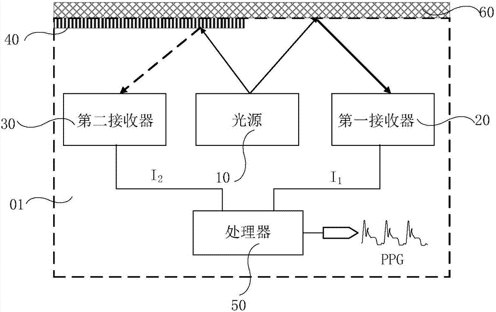
[0040] Embodiments of the present invention provide a Figure 3aThe photoelectric sensor 01 shown. The photoelectric sensor 01 includes a light source 10, a first receiver 20, a second receiver 30, and a human skin simulation layer 40 positioned on the light emitting side of the light source 10, the human skin simulation layer 40 and the light receiving side of the second receiver 30 corresponding to the location.

[0041] It should be noted that the light r...


PUM


Abstract

The invention provides a photoelectric sensor, a control method thereof, and a pulse detector, which relate to the technical field of photoelectric conversion and can reduce the probability of pulse signal distortion caused by motion interference when the photoelectric sensor is used to detect pulse. The photoelectric sensor includes a light source, a first receiver, a second receiver and a human skin simulation layer on the light emitting side of the light source, the human skin simulation layer corresponds to the light receiving side of the second receiver, and the first receiver is used to receive The optical signal generated by the reflected light of the user's skin is to be tested, and the first electrical signal is output after photoelectric conversion, and the second receiver is used to receive the optical signal generated by the reflected light of the human skin simulation layer, and the second electrical signal is output after the photoelectric conversion Signal. The photoelectric sensor also includes a processor connected to the first receiver and the second receiver, used to receive the first electrical signal and the second electrical signal, and use the second electrical signal to negatively compensate the first electrical signal, and output pulse signal.

Description

technical field [0001] The invention relates to the technical field of photoelectric conversion, in particular to a photoelectric sensor, a control method thereof, and a pulse detector. Background technique [0002] The periodic contraction and relaxation of the human ventricle leads to the contraction and relaxation of the aorta, making the blood flow pressure propagate from the root of the aorta along the entire arterial system in the form of waves. This wave is called pulse wave. The comprehensive information of the shape, intensity, rate and rhythm presented by the pulse wave reflects to a large extent the blood flow characteristics of many physiological and pathological conditions in the human cardiovascular system, so the pulse wave is an important physiological parameter of the human body. [0003] There are many kinds of sensors for pulse wave detection in the prior art. Among them, photoelectric sensors have been widely used in pulse wave measurement systems because...

Claims


Application Information

Patent Timeline
Patent Type & Authority Patents(China)
IPC IPC(8): A61B5/02A61B5/00
CPCA61B5/0064A61B5/02A61B5/7207A61B5/7235A61B5/02427A61B5/1495A61B5/7214A61B2560/0233A61B2560/0238A61B2560/0223A61B2562/0238
Inventor 袁佐
Owner BOE TECH GRP CO LTD
Why Eureka
Try Eureka