Linear accelerator

A technology of a linear accelerator and a multi-leaf collimator, which is applied in the field of medical devices and can solve the problems of heavy handpiece weight, unfavorable handpiece rotation angle, speed, and adjustment, etc.

Inactive Publication Date: 2017-01-18
SHANGHAI UNITED IMAGING HEALTHCARE
View PDF4 Cites 6 Cited by
  • Summary
  • Abstract
  • Description
  • Claims
  • Application Information

AI Technical Summary

Problems solved by technology

However, for a helical tomotron, the same as the linear accelerator, the collimator also needs to be installed at the head, and the head needs to be mounted with the collimator to rotate together. The weight of the head is relatively large, and the inertia of the head rotation is large, which is not conducive to The adjustment of the rotation angle and speed of the handpiece; the collimator will also be affected by gravity and centrifugal force when rotating, which will have an adverse effect on the control of radiation dose

Method used


Image

  • Linear accelerator
  • Linear accelerator

Examples


Embodiment 1

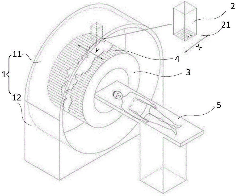
[0022] Such as figure 1 As shown, the embodiment of the present invention provides a linear accelerator, including: a frame 1, a head 2 and an annular carrier 3, the annular carrier 3 is fixed to the frame 1 and defines a longitudinal axis; the machine The head 2 is connected to the frame 1 and can rotate around the longitudinal axis on the radially outside of the annular carrier 3. The head 2 includes a radiation source (not shown) and a The first collimating device 21 on the ray path, the first collimating device 21 includes many pairs of adjacent blades; the second collimating device 4 is fixed on the annular carrier 3, and the second collimating device 4 The device 4 includes multiple pairs of blades adjacent to each other so as to be able to define an annular closed field around the longitudinal axis; wherein, in operation, the multiple pairs of blades of the first collimating device 21 are oriented in a first direction, so The pairs of blades of the second collimating d...

Embodiment 2

[0031] In the first embodiment, the frame 1 includes an annular portion 11 and a base 12 fixed to each other, the annular carrier 3 is fixed on the annular portion 11 and / or the base 12, and the machine head 2 needs to cooperate with the annular slide rail to realize the Mutual movement between the annular carrier 3 and the second collimation device 4 .

[0032] Different from Example 1, please refer to figure 2 , in this embodiment, the frame 1 includes a rotating part 13 and a base 12, the rotating part 13 is connected to the base 12, and can rotate around the longitudinal axis on the base 12 , the machine head 2 is fixed on the rotating part 13 . Since the rotating part 13 can rotate circumferentially, preferably at a full angle of 360 degrees, when the rotating part 13 rotates, it can drive the machine head 2 to rotate around the annular carrier 3 and the second collimating device 4 .

[0033] In this embodiment, the annular carrier 3 is fixed on the base. For example,...

Embodiment 3

[0036] Different from Embodiment 1 and Embodiment 2, in this embodiment, there are multiple heads 2 .

[0037] A plurality of the handpieces 2 can be respectively equipped with the acceleration tubes of different energy beams, so that the linear accelerator provided in Embodiment 3 can realize multi-energy simultaneous beam output therapy. For example, the number of the machine heads 2 is two, and the angle between the two machine heads 2 is 90 degrees, but it is not limited thereto.

[0038] In addition, at least one handpiece 2 can also be used as an imaging beam emitting part, and a detector can be arranged opposite to the handpiece as a receiving part of the imaging beam, so that imaging can be performed before, during and / or after treatment .

[0039] For other technical features in Embodiment 3, please refer to Embodiment 1 and Embodiment 2, and details will not be repeated here.

[0040] The embodiment of the present invention provides a linear accelerator. The head is ...


PUM


Abstract

The invention provides a linear accelerator. The linear accelerator comprises a frame, a machine head and an annular carrier. The annular carrier is fixed to the frame and limits a vertical axis. The machine head is connected to the frame and can rotate about the vertical axis on an radial outer side of the annular carrier. The machine head comprises a radiation source and a first collimating device. The first collimating device comprises multiple pairs of blades, wherein each two blades are adjacent to each other. A second collimating device is fixed to the annular carrier. The second collimating device comprises the multiple pairs of blades so that the second collimating device can be limited into an annular closed field around the vertical axis, wherein each two blades are adjacent to each other. During operation, the multiple pairs of blades of the first collimating device are oriented to a first direction, and the multiple pairs of blades of the second collimating device are oriented to a second direction which forms an angle with the first direction. The invention provides the linear accelerator, a rotation structure is light so that adjusting precision of an angle is increased; a dosage deviation caused by gravity and centrifugal force influences is avoided; and requirements to a motion frequency and a speed of the blades are reduced and a servicel life of a collimator is prolonged.

Description

technical field [0001] The invention relates to a medical device for radiotherapy, especially a linear accelerator. Background technique [0002] The accelerator used in radiotherapy is usually a linear accelerator or a helical tomoaccelerator (TomoTherapy). [0003] The head of the linear accelerator is installed on the frame, including the beam output device and the multi-level collimator, etc. During the treatment, the ray beam can treat the target area of ​​the patient at different angles through the rotation of the frame. At present, most linear accelerator heads are equipped with two to three-stage collimators to modulate the radiation. Therefore, the structure of the head is relatively complicated, and it needs to involve issues such as position arrangement, water-cooled motors, and wiring. The speed of the rack and the continuous rotation angle And the control accuracy has certain limitations. [0004] The spiral tomography accelerator uses the principle of CT, ins...

Claims


Application Information

Patent Timeline
Patent Type & Authority Applications(China)
IPC IPC(8): A61N5/10
CPCA61N5/1028A61N5/1045A61N5/1081A61N2005/1019A61N2005/1089A61N2005/1092
Inventor 王益锋张一戈龚飞
Owner SHANGHAI UNITED IMAGING HEALTHCARE
Why Eureka
Try Eureka