
An inner container component and a clothes dryer provided with the inner container component

A technology of liners and components, applied in the field of clothes dryers, can solve the problems of low heat source drying efficiency, potential safety hazards, and long drying time, and achieve the effects of saving post-processing, fast speed, and stable frame structure

Active Publication Date: 2018-10-19
GUANGDONG MIDEA KITCHEN APPLIANCES MFG CO LTD +1
View PDF5 Cites 0 Cited by
  • Summary
  • Abstract
  • Description
  • Claims
  • Application Information

AI Technical Summary

Problems solved by technology

[0004] (1) The technical problem to be solved by the present invention is: the existing dryer liner assembly rotates under the drive of the belt, so its structure is unstable, and potential safety hazards are prone to occur; The back of the liner, but they all use PTC ceramic heating or metal heating tubes, and the drying efficiency of the above heating sources is low and the drying time is long

Method used


Image

  • An inner container component and a clothes dryer provided with the inner container component
  • An inner container component and a clothes dryer provided with the inner container component
  • An inner container component and a clothes dryer provided with the inner container component

Examples


Embodiment 1

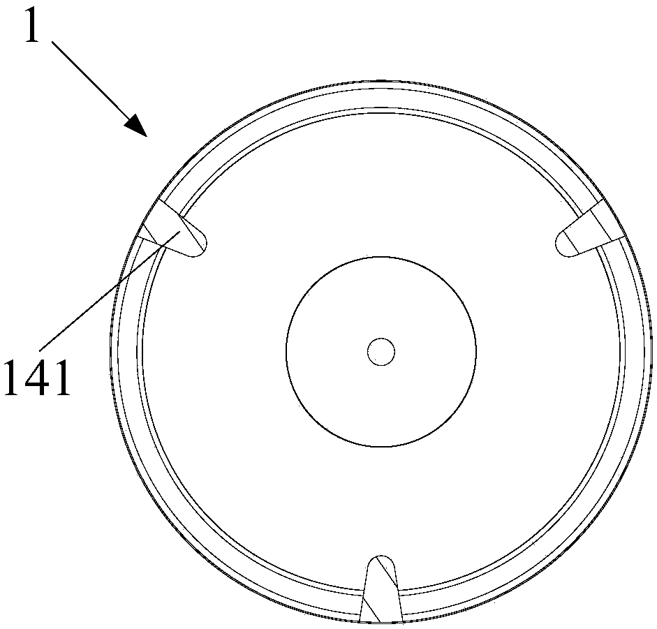
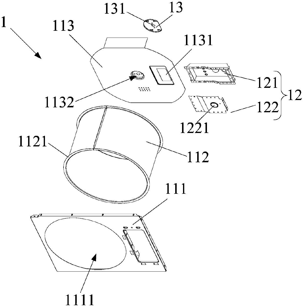
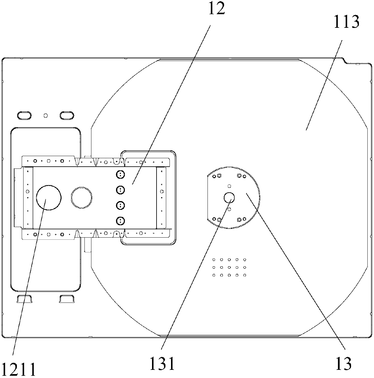
[0035] Such as Figure 2 to Figure 7 As shown, the liner assembly 1 provided in this embodiment includes a waveguide 12 and a liner body 11 with an open front end. A receiving cavity with an open front end is formed in the liner body 11. A waveguide port 1131 is provided on the liner body 11. , the entrance 1211 of the waveguide 12 communicates with the microwave emission end of the magnetron, and the exit 1221 of the waveguide 12 communicates with the accommodation cavity through the waveguide port 1131; wherein, as image 3 and Figure 4 As shown, the waveguide 12 includes a tube body 121 and a cover body 122, and the cover body 122 covers the tube body 121 and forms a guide cavity between the tube body 121; the inlet 1211 is located at On the tube body 121, the outlet 1221 is arranged on the cover 122, and both the inlet 1211 and the outlet 1221 are in communication with the guide cavity, and the waveguide 12 converts the magnetron generated The electromagnetic wave is gu...

Embodiment 2

[0047] Such as Figure 8 As shown, the technical solution of this embodiment is substantially the same as that of Embodiment 1, and the main difference is that the liner body 11 in this embodiment is an integrated structure, that is, the side plate 112 and the bottom plate 142 are made of metal materials Integral stretching and forming constitutes a metal cylinder-like structure. The metal cylinder is a stretched hardware piece produced by oil pressure. The diameter of the metal cylinder gradually increases from the back to the front. The front plate 111 is welded on the The front end of the side plate 112, the rear end of the liner body 11 is provided with a recessed area 1132, the rear end of the mounting plate 1423 is provided with a protrusion 1426 that matches the recessed area 1132, and the inner diameter of the recessed area 1132 is larger than The outer diameter of the protrusion 1426, the stirring frame 14 is not in contact with the inner wall of the liner body 11, th...


PUM


Abstract

The invention relates to the technical field of household appliances, in particular to an inner container assembly and a clothes dryer using the inner container assembly. The liner assembly provided by the present invention includes a waveguide and a liner body with an open front end. A receiving cavity with an open front end is formed in the liner body. A waveguide port is provided on the liner body. The outlet of the waveguide communicates with the cavity through the waveguide opening. Compared with the existing liner assembly, the liner assembly provided by the application uses the microwave generated by the magnetron as the heating source, and the body of the liner is provided with a waveguide port, and the microwave generated by the magnetron passes through the body of the liner through the waveguide The waveguide port on the top is sent into the accommodating cavity inside the inner tank body to dry and heat the clothes to be cleaned. The drying efficiency of microwave heating is high, and the drying speed of clothes is fast. With the sterilizing function, the user can dry the clothes in a short time.

Description

technical field [0001] The invention relates to the technical field of household appliances, in particular to an inner container assembly and a clothes dryer provided with the inner container assembly. Background technique [0002] Clothes dryers are clothes processing equipment used to dry clothes. Existing clothes dryers mainly include a drum, a drive motor, a blower fan and a heating device. The drive motor is used to drive the drum to rotate, and the drum is used to accommodate There are several stirring rods inside the drum, and the drum rotates to drive the stirring rods to disperse the dried clothes. The heating device uses the high-temperature resistance heat generated by the resistance or the combustion heat generated by the combustion gas to heat the air in the drum or The hot air is passed into the drum and exchanges heat with the dehydrated clothes, so that the water seal in the clothes evaporates, and then the clothes are dried. The blower is used to blow air in...

Claims


Application Information

Patent Timeline
Patent Type & Authority Patents(China)
IPC IPC(8): D06F58/20D06F58/26
CPCD06F58/20D06F58/266
Inventor 刘君君唐相伟李伟
Owner GUANGDONG MIDEA KITCHEN APPLIANCES MFG CO LTD
Learn More