Impeller, centrifugal pump and electric drive pump

A technology of impellers and blades, applied in the field of impellers, can solve the problems of small impeller diameter, small volume, small overall size of centrifugal pumps, etc., and achieve the effect of improving hydraulic efficiency

Inactive Publication Date: 2017-01-18
ZHEJIANG SANHUA AUTOMOTIVE COMPONENTS CO LTD
View PDF8 Cites 13 Cited by
  • Summary
  • Abstract
  • Description
  • Claims
  • Application Information

AI Technical Summary

Problems solved by technology

[0004] In recent decades, centrifugal pumps, especially electric-driven centrifugal pumps, have been widely used in thermal cycle systems; at present, thermal cycle systems are developing towards high performance and compactness, so the installation space of centrifugal pumps is limited and the performance requirements are high; due to the The overall size is small and the volume is small, so the diameter of the corresponding impeller is also small. In this case, it is difficult for the impeller of the traditional centrifugal pump to meet the requirements of high head and high efficiency at low specific speed and low flow rate.

Method used


Image

  • Impeller, centrifugal pump and electric drive pump
  • Impeller, centrifugal pump and electric drive pump
  • Impeller, centrifugal pump and electric drive pump

Examples


Embodiment Construction

[0043] The present invention will be further described below in conjunction with accompanying drawing and specific embodiment:

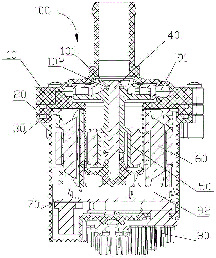
[0044] figure 1It is a structural schematic diagram of an electric drive pump 100, which includes an impeller chamber cover 10, an isolation sleeve 20, a motor housing 30, a pump shaft 40, a rotor assembly 50, a stator assembly 60, an electric control board 70, and a cooling assembly 80; the inner chamber of the pump includes the space between the impeller chamber cover 10 and the motor housing 30, and the spacer sleeve 20 divides the inner chamber of the pump into a flow chamber 91 and an accommodating chamber 92. The flow chamber 91 can have a working medium flowing through it, and the rotor The component 50 is set in the flow cavity 91, the cavity 92 has no working medium, the stator component 60 and the electric control board 70 are set in the cavity 92; the pump shaft 40 and the isolation sleeve 20 are fixed by injection molding, and the rotor c...


PUM


Abstract

The invention discloses an impeller which comprises an upper cover plate, blades and a lower cover plate; the blades and the upper cover plate are formed by integral injection molding; the blades are formed on the lower surface of the upper cover plate and are composed of long blades and short blades; the arc length of each long blade is larger than that of each short blade; the long blades are uniformly distributed along the circumference of the upper cover plate; the long blades and the short blades are arranged alternatively in the circumferential direction of the upper cover plate; each long blade is composed of a first head part and a first tail part; each short blade is composed of a second head part and a second tail part; the first tail parts and the second tail parts are aligned at the outer edge of the upper cover plate; and the outer edge of the upper cover plate is a first circumference with the diameter being phi 1, and the second head part of each short blade is arranged on a second circumference with the diameter being phi 2, wherein the diameter phi 2 of the second circumference is 0.6-0.7 times of the diameter phi 1 of the first circumference, thus the impeller with such arrangement is beneficial to improving the hydraulic efficiency and increasing the lift.

Description

[0001] 【Technical field】 [0002] The invention relates to an impeller, in particular to a centrifugal pump with an impeller. [0003] 【Background technique】 [0004] In recent decades, centrifugal pumps, especially electric-driven centrifugal pumps, have been widely used in thermal cycle systems. At present, thermal cycle systems are developing towards high performance and compactness, so the installation space of centrifugal pumps is limited and the performance requirements are high; due to the The overall size is small and the volume is small, so the diameter of the corresponding impeller is also small. In this case, it is difficult for the impeller of the traditional centrifugal pump to meet the requirements of high head and high efficiency at low specific speed and low flow rate. [0005] Therefore, it is necessary to improve the existing technology to solve the above technical problems. [0006] 【Content of invention】 [0007] The object of the present invention is to p...

Claims


Application Information

Patent Timeline
Patent Type & Authority Applications(China)
IPC IPC(8): F04D29/22F04D29/24F04D29/58F04D13/06
CPCF04D13/0606F04D29/2222F04D29/242F05B2230/20F05B2230/22F05B2240/30F05B2280/6003F04D1/00F04D13/06F04D17/08F04D25/0606F04D29/02F04D29/30F04D29/5813F28F99/00F28F2250/08
Inventor 不公告发明人
Owner ZHEJIANG SANHUA AUTOMOTIVE COMPONENTS CO LTD
Why Eureka
Try Eureka