Thermal shock furnace

A technology of thermal shock and furnace, which is applied in the field of thermal shock resistance experiment, can solve the problems affecting the accuracy and authenticity of the test results, and achieve the effect of simple structure, fast unloading and reducing operation errors

Inactive Publication Date: 2017-01-18
UNIV OF JINAN
View PDF5 Cites 0 Cited by
  • Summary
  • Abstract
  • Description
  • Claims
  • Application Information

AI Technical Summary

Problems solved by technology

This process will be affected by the size and quantity of the sample, the position of the sample in the furnace, the position of the furnace door, the size and structure, the distance from the furnace mouth to the cooling medium, the indoor temperature and the proficiency of the operator, etc. The accuracy and authenticity of the test results

Method used


Image

  • Thermal shock furnace
  • Thermal shock furnace
  • Thermal shock furnace

Examples


Embodiment Construction

[0022] The present invention will be further defined below in conjunction with the accompanying drawings and specific embodiments.

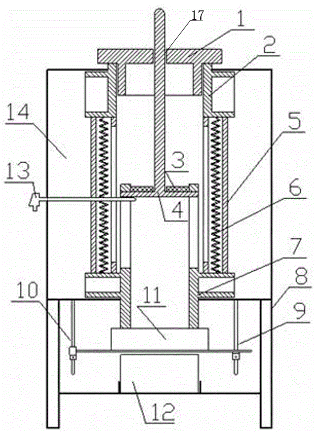
[0023] Such as figure 1 As shown, a thermal shock furnace includes a furnace shell 8, a furnace 5 positioned on the furnace shell 8, and a heating element 6 located in the furnace 5. A barrier sleeve 7 is arranged in the furnace 5, and the sleeve part of the barrier sleeve 7 Inserted into the furnace 5, the fence part of the fence sleeve 7 is located below the furnace 5.

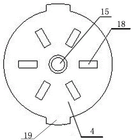
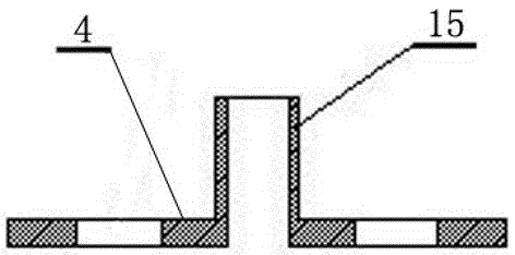
[0024] A sample heating chamber is formed inside the furnace 5, and the upper sample tray 3 and the lower sample tray 4 are arranged up and down in the sample heating chamber, grooves are opened on the top side wall of the fence sleeve, and lugs 19 are provided on the upper and lower sample trays. , The lugs 19 on the upper and lower sample trays are located in the grooves on the top side wall of the fence sleeve. The center of the upper sample tray 3 is provided with a first...


PUM


Abstract

The invention discloses a sample tray of a thermal shock furnace.The sample tray of the thermal shock furnace is simple in structure, convenient in operation, fast in unloading, reduced in operation error and more accurate in the experiment result. By means of a grating sleeve with a supporting sample disk, the support of the sample is conveniently supported, taken out and placed, and the sample is heated uniformly on the tray. At the same time, when the sample tray is not in the thermal shock test, the electric furnace retains the heating function of the ordinary electric furnace. The rotary furnace bottom cover is added to the furnace body, which is favorable for fast opening and closing of furnace body heat preservation and convenient quenching experiment.

Description

technical field [0001] The invention relates to a thermal shock furnace, which is used for the thermal performance test of inorganic materials, especially the thermal shock resistance test of glass ceramics and refractory materials. Background technique [0002] Thermal shock resistance generally adopts the rapid cooling method, and the experimental results are affected by the speed of the rapid cooling process of the sample. In the thermal shock test, the sample is first processed to a certain temperature and then quenched. Usually it is a manual sampling operation, and the sample is quickly placed from a high temperature to a low temperature medium. This process will be affected by the size and quantity of the sample, the position of the sample in the furnace, the position of the furnace door, the size and structure, the distance from the furnace mouth to the cooling medium, the indoor temperature and the proficiency of the operator, etc. The accuracy and authenticity of...

Claims


Application Information

Patent Timeline
IPC IPC(8): F27B17/02F27D1/18F27D11/00
CPCF27B17/02F27D1/1808F27D11/00
Inventor 刘世权宋廷寿
Owner UNIV OF JINAN
Why Eureka
Try Eureka