
Flexible display panel, its preparation method, and flexible display device

A flexible display and flexible substrate technology, applied in the direction of climate sustainability, final product manufacturing, sustainable manufacturing/processing, etc., can solve problems such as drift, contact hole and channel area wear signals, poor display, etc., to reduce Effects of stress variation, reduced wear, and improved overall stability

Active Publication Date: 2017-01-18
XIAMEN TIANMA MICRO ELECTRONICS +1
View PDF7 Cites 46 Cited by
  • Summary
  • Abstract
  • Description
  • Claims
  • Application Information

AI Technical Summary

Problems solved by technology

[0004] At present, the bending resistance of flexible OLED displays is very different. For example, the flexibility of the mainstream LTPS-OLED thin film transistor is not good, mainly because the contact hole and the channel area are easy to wear and tear during bending deformation, resulting in signal drift. cause bad display

Method used


Image

  • Flexible display panel, its preparation method, and flexible display device
  • Flexible display panel, its preparation method, and flexible display device
  • Flexible display panel, its preparation method, and flexible display device

Examples


Embodiment 1

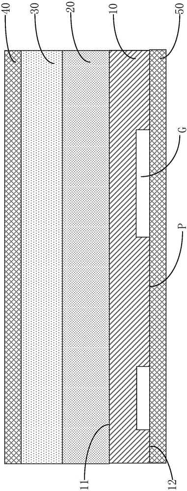
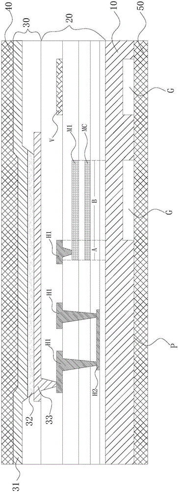
[0032] Such as figure 1 and figure 2 As shown, two schematic cross-sectional views of a flexible display panel provided by Embodiment 1 of the present invention, wherein figure 1 It is a schematic cross-sectional view of one part of the flexible display panel, which only roughly shows the basic structural composition; figure 2 It is a detailed cross-sectional schematic diagram of another part of the flexible display panel.

[0033] Such as figure 1 As shown, the flexible display panel of Embodiment 1 includes: a flexible substrate 10 , a TFT array layer 20 , a display layer 30 , a front protective film 40 and a rear protective film 50 .

[0034] Wherein, the flexible substrate 10 has a first surface 11 and a second surface 12; wherein, the first surface 11 is figure 1 As shown on the upper surface of the flexible substrate 10, the second surface 12 is figure 1 The lower surface of the flexible substrate 10 is shown.

[0035] In this embodiment, the flexible substrate 1...

Embodiment 2

[0082] like Figure 7 As shown, the schematic cross-sectional view of the flexible display panel of Embodiment 2, the difference between the flexible display panel of Embodiment 2 and Embodiment 1 lies in the structure of the flexible substrate 10 .

[0083] The flexible substrate 10 of Example 2 has a structure in which multiple layers of flexible substrate films 10a are stacked in sequence.

[0084] In a specific embodiment of the present invention, the flexible substrate film 10a can use conventional flexible substrate materials such as PI or PET.

[0085] In Embodiment 2, the flexible substrate 10 is formed by stacking multiple layers of PI films sequentially; Figure 7 As shown, the PI film forming the second surface 12 is the lowermost PI film.

[0086] The second surface 12 of the flexible substrate 10 (the lower surface of the lowermost PI film) has a concave-convex patterned structure, which is the same as that of Embodiment 1, and details will not be repeated here....

Embodiment 3

[0088] like Figure 8 As shown, a schematic cross-sectional view of the flexible display panel of Embodiment 3, the difference between the flexible display panel of Embodiment 3 and Embodiment 1 lies in the structure of the flexible substrate 10 .

[0089] The flexible substrate 10 of the third embodiment has a structure in which flexible substrate films 10a and inorganic films 10b are alternately stacked, and the first surface 11 and the second surface 12 are formed by the flexible substrate films 10a.

[0090] In a specific embodiment of the present invention, the flexible substrate film 10a can use conventional flexible substrate materials such as PI or PET; the inorganic film 10b can be made of silicon oxide or nitrogen oxide.

[0091] In Example 3, the flexible substrate film 10a is a PI film, and the inorganic film 10b is a silicon oxide film.

[0092] The second surface 12 of the flexible substrate 10 (the lowermost flexible substrate film 10 a ) has a concave-convex p...


PUM


Abstract

The invention relates to a flexible display panel, its preparation method, and a flexible display device. The flexible display panel of the present invention comprises a flexible substrate, a TFT array layer, a display layer, a front plate protection film and a back plate protection film. The flexible substrate has an uneven patterning structure and the part of the flexible substrate corresponding to the punching and channel region of the TFT array layer with poor flexural stress is thickened. And the other part of flexible substrate with good flexural stress remains relatively thin. This design reduces the change in flexural stress during the bending led deformation in an area with poor flexural stress and reduces wearing as well. In addition, the uneven patterning design is beneficial to the dispersion of flexural stress and to increase the overall stability of the flexible display panel.

Description

technical field [0001] The invention relates to a flexible display panel, a preparation method thereof, and a flexible display device. Background technique [0002] A flexible display needs to use a flexible organic material, such as polyimide (PI) or polyethylene terephthalate (PET), to make a substrate, so that the entire display device can be bent and deformed. Due to its bending and deformation function, low power consumption, and small size, flexible displays have gradually become displays used in many fields. [0003] The current manufacturing process of flexible displays, taking flexible OLED displays as an example, roughly includes the following steps: First, apply flexible materials on a rigid substrate (such as a glass substrate) to make a flexible substrate, then make an OLED device on the flexible substrate, and Encapsulate the OLED device and paste the front panel protective film; finally peel off the rigid substrate (for example, use a laser to separate the fl...

Claims


Application Information

Patent Timeline
Patent Type & Authority Applications(China)
IPC IPC(8): H01L27/12H01L51/52H01L21/77
CPCH01L27/1218H01L27/1262H10K77/111Y02E10/549Y02P70/50
Inventor 林鸿于泉鹏魏丹萍世良贤二
Owner XIAMEN TIANMA MICRO ELECTRONICS
Learn More