Motor

A casing and bearing seat technology, applied in the field of electric motors, can solve problems such as reducing friction, and achieve the effects of reducing friction, good cooling effect, and good effect

Active Publication Date: 2017-01-18
NINGBO JUNWEI ELECTRICAL
View PDF7 Cites 7 Cited by
  • Summary
  • Abstract
  • Description
  • Claims
  • Application Information

AI Technical Summary

Problems solved by technology

[0005] In view of the above-mentioned problems existing in the prior art, it is now intended to provide a motor that selects roller bearings to be sleeved on the main shaft to reduce friction and at the same time strengthen the radial load, and to set the inlet and outlet on the bearing seat. The oil hole provides a continuous oil supply system for the bearings, and solves the problem of manually adding lubricating oil. A groove is set in the motor casing to make the coolant circulate in the casing to achieve the effect of continuous cooling. The transformer is used as the sensing and measurement of the angular position to make the motor run more stably, and by setting up multi-layer seals, and opening oil outlet holes connected to the outside world on each layer of seals, it is ensured that the lubricating oil will not flow into the casing It affects the normal operation of the motor, and can also achieve the effect of cooling

Method used


Image

  • Motor
  • Motor
  • Motor

Examples


Embodiment Construction

[0027] In order to make it easy to understand the technical means, creative features, goals and effects achieved by the present invention, the following examples are combined with the appended figure 1 To attach Figure 8 The technical solutions provided by the present invention are described in detail, but the following content is not intended as a limitation of the present invention.

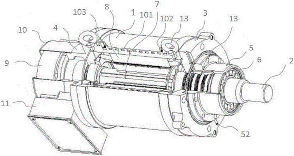
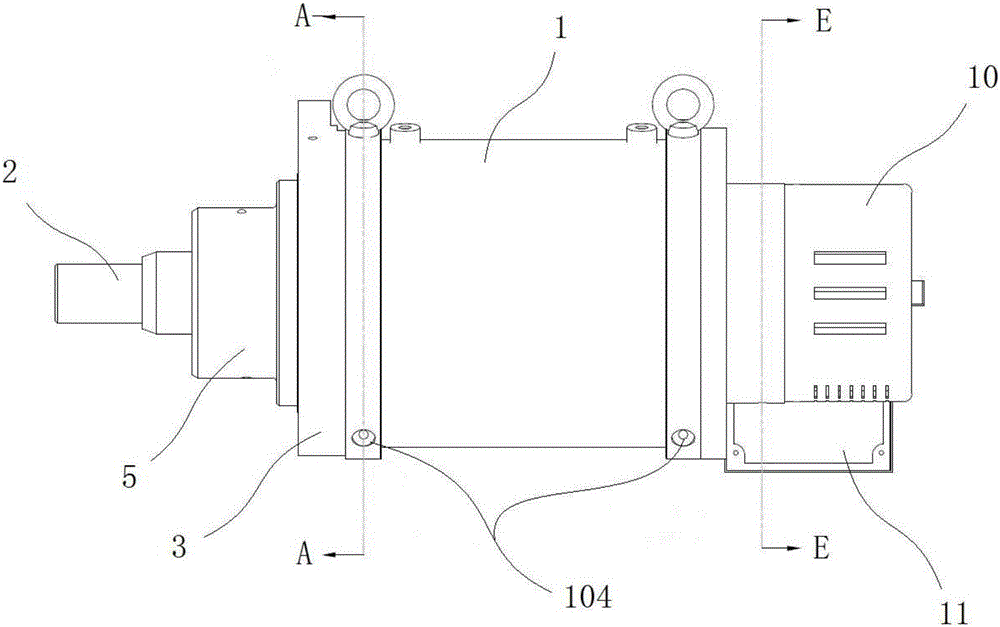
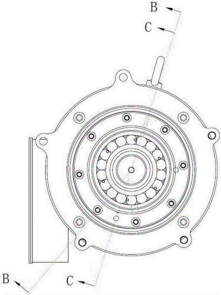
[0028] figure 1 It is a structural diagram of an embodiment of a motor of the present invention; figure 2 It is a structural diagram of a viewing angle of a preferred embodiment of the present invention; image 3 for figure 2 The cross-sectional view of A-A in the middle; Figure 4 for image 3 The cross-sectional view of B-B in the middle; Figure 5 for image 3 Sectional view of C-C in middle; Figure 6 for figure 2 Sectional view of D-D in middle; Figure 7 for figure 2 Sectional view of E-E in middle; Figure 8 for Figure 5 Enlarged view of part A in Fig. Such as figure...


PUM


Abstract

The invention, which belongs to the technical field of the motor, provides a motor comprising a case, a main shaft, end covers, a bearing seat, moving parts, a bearing and control parts. The moving parts include a permanent-magnet rotor and a stator winding. The control parts include a rotating transformer and a junction box. A main shaft is arranged in the hollow space of the case coaxially. The moving parts are arranged between the case and the main shaft. The end covers are arranged at the two ends of the case; an oil supply hole is formed in the front end cover and is communicated with a channel, thereby realizing effects of lubrication and cooling. A framework oil seal is arranged between the main shaft and the bearing seat so as to realize a better sealing effect. Oil control rings are arranged between the main shaft and the bearing seat and between the main shaft and the front end cover; light surfaces of the oil control rings correspond to oil storage grooves; second oil outlets are formed in the oil storage grooves; and thus a cooling effect is realized. Third oil outlets are formed in the stator winding, so that a liquid discharging effect is good. Besides, a tail-end inclined oil channel is arranged on the rear cover, so that safety oil discharging is realized and the security is high. And with the rotating transformer, angle and position sensing and measuring are realized and the operation becomes stable.

Description

technical field [0001] The invention relates to the technical field of motors, in particular to a motor. Background technique [0002] With the development of electric energy, electric energy plays an important role in people's production and life. From a small perspective, most equipment needs to be driven. At present, the most important driving method is to use motor drive. Therefore, the motor's Research has come into the spotlight. [0003] However, the motors currently on the market basically use rolling bearings as an effective way to reduce friction, and the lubrication effect on the bearings is not ideal, requiring long-term and continuous manual adding of lubricating oil, which brings a certain workload to the user, which is not suitable for machines. The modern design concept, and the radial load capacity of the rolling bearing is poor; and the motor shell is set into a fin shape as the main way of heat dissipation, which is difficult to process, and the heat diss...

Claims


Application Information

Patent Timeline
Patent Type & Authority Applications(China)
IPC IPC(8): H02K5/173H02K5/20H02K9/193H02K11/21
CPCH02K5/173H02K5/20H02K9/193
Inventor 刘洪明
Owner NINGBO JUNWEI ELECTRICAL
Why Eureka
Try Eureka