
Intelligent vibratory massage system for foot reflection zones and massage control method

A reflective area, intelligent technology, applied in vibration massage, program control, computer control, etc., can solve the problems of unable to prepare reflective area, no temperature control device, high labor intensity, etc.

Inactive Publication Date: 2017-01-25
XIAN UNIV OF SCI & TECH
View PDF8 Cites 1 Cited by
  • Summary
  • Abstract
  • Description
  • Claims
  • Application Information

AI Technical Summary

Problems solved by technology

However, as the cleanest traditional Chinese medicine massage therapy method, it has not been widely promoted.
Traditional Chinese medicine massage requires experienced massage experts to perform manual massage, which has been unable to effectively solve problems such as high labor intensity, inconsistent expert techniques, and a small number of experts.
The existing foot massagers mainly have the following problems: first, they cannot perform precise, systematic and orderly massages on the reflection areas of the soles of the feet, and mainly focus on the overall vibration; second, they cannot prepare and know in time the details of the current massage Reflection area; third, it is impossible to control the massage time of specific acupoints corresponding to the reflection area; fourth, there is no temperature control device, and the temperature of foot massage cannot be controlled

Method used


Image

  • Intelligent vibratory massage system for foot reflection zones and massage control method
  • Intelligent vibratory massage system for foot reflection zones and massage control method
  • Intelligent vibratory massage system for foot reflection zones and massage control method

Examples


Embodiment Construction

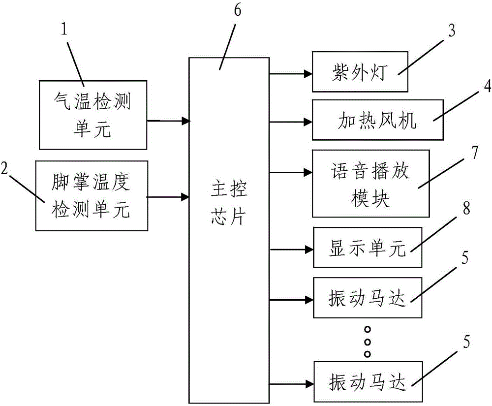
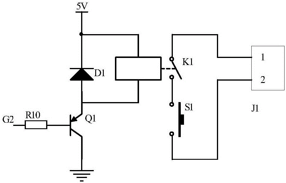
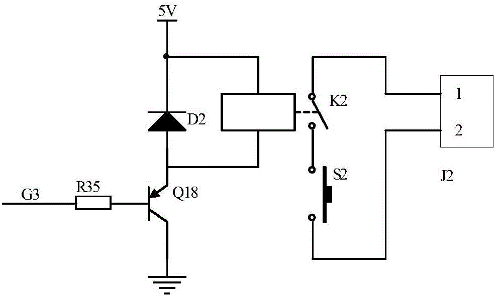
[0059] Such as figure 1 The intelligent vibration massage system for the foot reflection area shown includes an external casing, an air temperature detection unit that detects the air temperature 1, a sole temperature detection unit that detects the temperature of the sole of the person being massaged, 2 for sterilization and disinfection The ultraviolet lamp 3, the heating fan 4 that heats the sole of the person being massaged, a plurality of vibration motors 5 that respectively massage the reflection area of ​​the sole of the person being massaged, and the electronic circuit board arranged in the outer shell, the The electronic circuit board is provided with a main control chip 6 and a timing circuit 7 connected to the main control chip 6, each of the vibration motors 5 is located under one of the sole reflection areas, and a plurality of the vibration motors 5 are controlled by the master The chip 6 is controlled and connected to the main control chip 6; the air temperature d...


PUM


Abstract

The invention discloses an intelligent vibratory massage system for foot reflection zones and a massage control method. The massage system comprises an outer casing, an air temperature detection unit, a foot sole temperature detecting unit, an ultraviolet lamp, a heating fan, a plurality of vibrating motors for massaging the foot reflection zones of a massaged person respectively and an electronic circuit board arranged in the outer casing, wherein a master control chip and a timing circuit are arranged on the electronic circuit board, each vibrating motor is located below the corresponding foot reflection zone, the vibrating motors, the air temperature detection unit and the foot sole temperature detection unit are all connected with the master control chip, and the ultraviolet lamp and the heating fan are both controlled by the master control chip. The massage control method comprises the steps as follows: firstly, sterilization; secondly, heating starting; thirdly, vibratory massage. The system is reasonable in design, simple and convenient to use and good in use effect; by means of the vibrating motors located under the foot reflection zones for vibratory massage, the massage sequence and the massage time for the foot reflection zones can be controlled simply and conveniently, and the vibratory massage effect is good.

Description

Technical field [0001] The invention belongs to the technical field of foot massage equipment, and particularly relates to an intelligent vibration massage system and a massage control method for a foot reflection area. Background technique [0002] The various organs and parts of the human body have corresponding areas on the feet, which can reflect the physiological and pathological information of the corresponding organs. This is the so-called "foot reflex area" (also called the sole reflex area). Using massage techniques to stimulate these reflex areas, the foot reflex areas can adjust the functions of various parts of the human body, and achieve the effects of disease prevention and treatment, and self-care. It is medically called the "foot reflex area health method". [0003] In China, traditional Chinese massage has a long history, and it is even more effective in traumatic treatment and health care. According to the theory of traditional Chinese medicine, a person has "fou...

Claims


Application Information

Patent Timeline
IPC IPC(8): A61H23/02A61H39/04A61F7/00G05B19/042
CPCG05B19/042A61F7/00A61H23/02A61H39/04A61F2007/0047A61F2007/006A61H2201/0207A61H2201/025A61H2201/10A61H2201/1207A61H2201/5007A61H2205/125
Inventor 汪梅赵海强徐长丰朱亮朱阳阳张松志牛钦
Owner XIAN UNIV OF SCI & TECH
Learn More