Machining method of sliding block cavity formed through precision cold drawing and guiding rail pair

A forming method and a technology of guide rail pairs, which are applied in the direction of manufacturing tools, heat treatment equipment, quenching agents, etc., can solve the problems of oil fume, mineral oil easily heated, etc., to reduce production costs, improve market competitiveness, and reduce grinding time. Effect

Active Publication Date: 2017-01-25
JIAXING HAILINGDA PRECISION TRANSMISSION TECH CO LTD
View PDF8 Cites 3 Cited by
  • Summary
  • Abstract
  • Description
  • Claims
  • Application Information

AI Technical Summary

Problems solved by technology

Most of the conventional quenching agents use animal and vegetable oils or mineral oils for quenching, or add other additives, but animal and vegetable oils contain unsaturated fatty acids that will be hydrolyzed or oxidized to produce pungent odors, while mineral oils are prone to heat and produce fumes

Method used


Image

  • Machining method of sliding block cavity formed through precision cold drawing and guiding rail pair
  • Machining method of sliding block cavity formed through precision cold drawing and guiding rail pair
  • Machining method of sliding block cavity formed through precision cold drawing and guiding rail pair

Examples


Embodiment 11

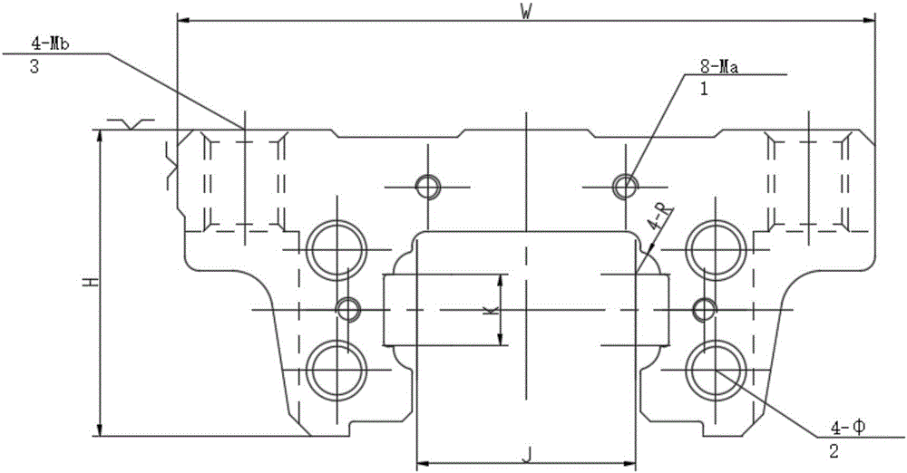
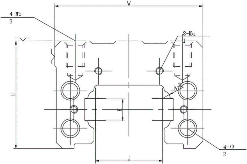
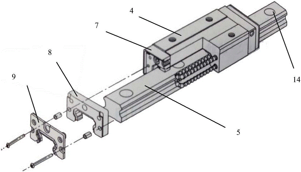
[0086] Such as Figure 3-7 As shown, a slider produced by the above method, the slider 4 and the guide rail 5 form a guide pair, the raceway of the slider is provided with rolling balls, and both ends of the slider are sequentially provided with a ball returner 7, a self-lubricator 8. The end sealing baffle 9. The self-lubricator includes a shell 81 and a high-density fiber net 82, an oil control board 83 and a high-oil fiber net 84 sequentially arranged in the shell, the high-oil fiber net is arranged at the end Seal one side of the baffle. The arrow in the figure shows the direction of lubricant flow 85. A rolling ball 6 is provided on the raceway 10, a ball holder 12 is provided between the rolling balls, a grease bag 13 is provided in the space between the rolling ball and the ball holder, and one end of the telescopic shield 11 is connected to the slider The end is sealed and fixed with the baffle, and the other end is fixed with the end of the guide rail. Grease bags c...


PUM

PropertyMeasurementUnit
thicknessaaaaaaaaaa
diameteraaaaaaaaaa

Abstract

The invention discloses a machining method of a sliding block cavity formed through precision cold drawing and a sliding block produced by adopting the method. The method comprises the steps that a sliding block is prepared, a precision cold drawing section bar is sawed into the sliding block with the length slightly greater than L by using a band sawing machine; two end faces are roughly milled, the front end face and the rear end face of a raw material block are milled by a horizontal milling machine to make the length of the sliding block basically equal to L; six surfaces are roughly grinded, namely the six surfaces of the sliding block are grinded by using a surface grinding machine, so that the width of the sliding block is equal to W, the height of the sliding block is equal to H, and the length of the sliding block is equal to L; return device holes and rolling ball through holes are drilled, namely the return device installing holes 8-Ma are dilled in the front and rear end faces of the sliding block and rolling ball through holes (shown in the description) are drilled in the front and rear end faces of the sliding block by adopting a machining center, user installing holes are drilled, namely the user installing holes 4-Mb are drilled in the upper end face of the sliding block by adopting the machining center; heat treatment is performed, namely the sliding block is quenched and oxidized; accurate grinding is conducted on a reference surface; the reference surface is accurately grinded to reach the sizes W and H by using the surface grinding machine; rollaway forming grinding is performed, namely forming and accurate grinding of a rollaway 4-R are performed by using a grinding machine special for the sliding block.

Description

Technical field [0001] The invention belongs to the technical field of manufacturing of rolling linear guide pairs, and specifically relates to a method for processing a precision cold-drawn forming slider cavity and a guide rail pair. Background technique [0002] Rolling linear guide pair is a structure that plays a guiding role. In general machines, one component needs to move relative to another component, so support and guidance are required. Guide rails play this role. In machine tools and other machine tools, semiconductor manufacturing equipment , Industrial robots and other industrial equipment are widely used. The rolling linear guide pair is the sliding block sliding linearly on the guide rail, and only this one degree of freedom can ensure high relative motion accuracy and low speed flexibility. [0003] The slider is a component of the rolling linear guide pair. When the slider and the guide rail move relative to each other, the balls roll along the inner raceway of t...

Claims


Application Information

Patent Timeline
Patent Type & Authority Applications(China)
IPC IPC(8): B23P15/00C21D1/60
CPCB23P15/00C21D1/60
Inventor 孙亮向宝明
Owner JIAXING HAILINGDA PRECISION TRANSMISSION TECH CO LTD
Why Eureka
Try Eureka