
Frame type swinging cutting machine

A cutting machine and swing mechanism technology, applied in ceramic molding machines, manufacturing tools, etc., can solve problems such as low motion accuracy, wire rope breakage, and many intermediate connectors, optimize process layout, improve reliability, and simplify the structure of the cutting machine. Effect

Inactive Publication Date: 2017-01-25
山东阳光众泰机械工程有限公司
View PDF5 Cites 2 Cited by
  • Summary
  • Abstract
  • Description
  • Claims
  • Application Information

AI Technical Summary

Problems solved by technology

[0003] In view of the current problems in the vertical cutting of aerated concrete blocks, the present invention aims to provide a cutting machine with a frame-type swing mechanism. The use of this new type of frame-swing cutting machine can solve the above-mentioned intermediate problems in the process of vertical cutting. There are many connecting parts, low movement precision, and the steel wire rope breaks after the movement parts are worn, which simplifies the structure of the components and improves the reliability of the equipment.

Method used


Image

  • Frame type swinging cutting machine
  • Frame type swinging cutting machine
  • Frame type swinging cutting machine

Examples


Embodiment Construction

[0014] The present invention will be further described below in conjunction with accompanying drawing.

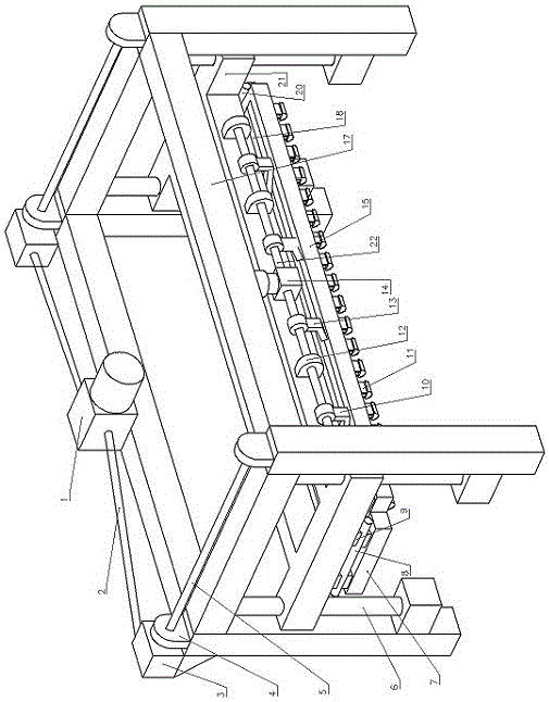
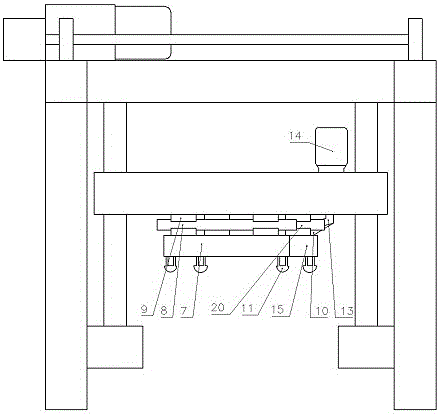
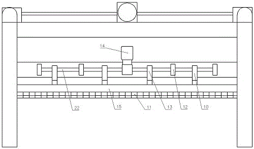
[0015] Such as Figure 1 to Figure 4 As shown, the present invention provides a cutting machine frame-type swing mechanism, which includes a body 17 with beams on both sides, a swing frame inside the body, and a lifting reducer 1 in the middle of the beam on one side of the body. There are respectively a reducer 3 connected to the lifting reducer, a vertical guide column 6 is provided on the legs of the frame, and a sprocket mechanism 4 connected by four synchronous shafts is provided at the top corner of the frame. The sprocket mechanism drives the inner swing frame to move up and down.

[0016] The swing frame includes an inner swing frame 15 and an outer swing frame 7. The two ends of the swing frame are respectively connected to linear guide rails 8 arranged horizontally. A small square frame-shaped fixed mount 21 and a swing motor 14 are arranged above the swing frame...


PUM


Abstract

The invention relates to manufacturing of aerated concrete production equipment, and provides a cutting machine frame type swinging cutting mechanism. The cutting machine frame type swinging cutting mechanism comprises a machine body, wherein cross beams are arranged at the two sides of the machine body; a swinging frame is arranged inside the machine body; a lifting speed reducing machine is arranged in the middle part of the cross beam formed in one side of the machine body; speed reducing machines in transmission connection with the lifting speed reducing machine are respectively arranged at the front side and the back side of the machine body; a swinging motor is connected with a transverse swinging shaft; the swinging shaft is connected with an inner side swinging frame and an outer side swinging frame through an inner side swinging arm and an outer side swinging arm; the inner side swinging frame and the outer side swinging frame forwards and backwards swing through being driven by the swinging shaft; a plurality of wire drawing tiles are respectively arranged under the inner side swinging frame and the outer side swinging frame. The cutting frame type swinging cutting machine has the advantages that the optimization of the process layout of the frame type swinging cutting on a green body is realized; the structure of a cutting machine is simplified; the reliability is improved; mechanisms of each part independently work; the connection structure is clear; the later-stage maintenance is simple.

Description

technical field [0001] The invention relates to the production of aerated concrete production equipment, in particular to a frame-type swing cutting machine. Background technique [0002] The existing aerated concrete vertical cutting equipment is basically in the form of a shaft pendulum. The structural principle is that four pairs of swing shafts are symmetrically distributed on both sides of the small box, and the shaft ends are connected by connecting rods. Arc tiles are used for cutting wire ropes, hanging and positioning. The vertical cutting of this installation method has two obvious disadvantages. First, there are many fixed components connected in the middle, and the movement accuracy is low. Second, it is difficult to install the four pairs of swing shafts. , The positioning accuracy is low, and it is easy to cause after long-term operation and wear. The swing is out of sync, causing the cutting wire rope to break, and the cut blank is prone to ghosting, forming d...

Claims


Application Information

Patent Timeline
Patent Type & Authority Applications(China)
IPC IPC(8): B28B11/14
CPCB28B11/14
Inventor 于成伟
Owner 山东阳光众泰机械工程有限公司
Learn More