A pipeline network monitoring and control system and a monitoring and control method realized by using the system
A monitoring and control, pipeline network technology, applied in pipeline systems, special data processing applications, data processing input/output processes, etc., can solve the problems of lack of monitoring system, inability to timely control pipelines, and inability to grasp the status of underground pipelines in a timely manner. Achieve the effect of ensuring reliability and stability, high reliability, automatic and effective control
- Summary
- Abstract
- Description
- Claims
- Application Information
AI Technical Summary
Problems solved by technology
Method used
Image
Examples
specific Embodiment approach 1
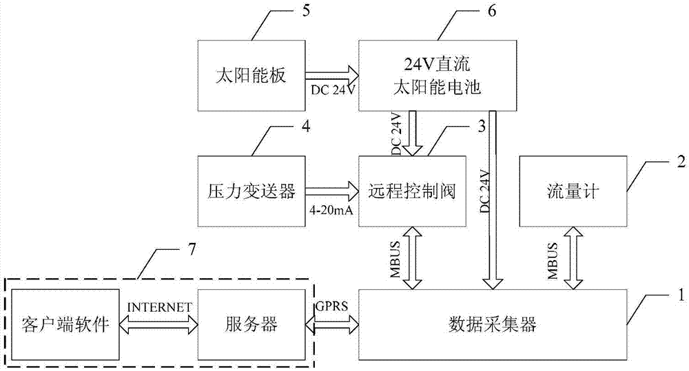
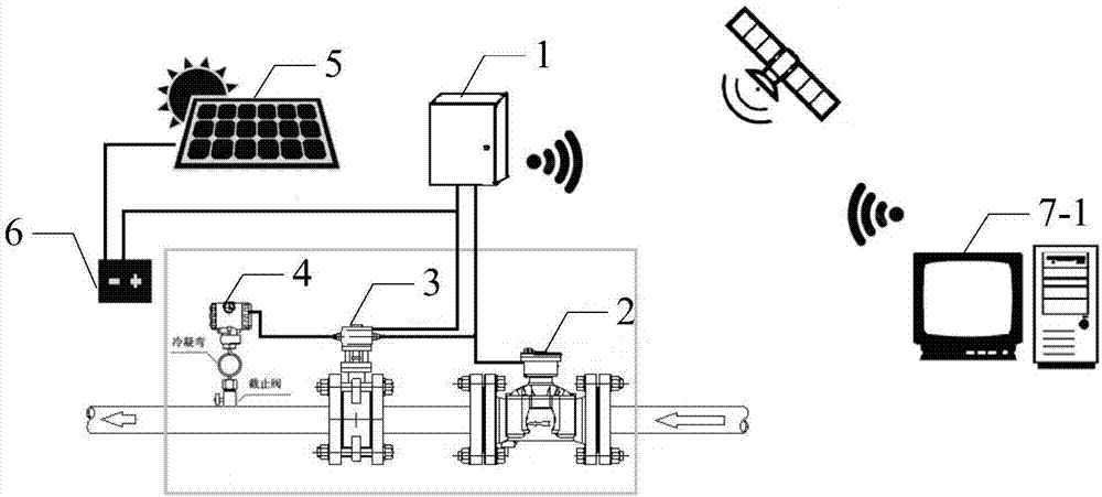
[0042] Specific implementation mode one: refer to figure 1 and figure 2 Specifically explain this embodiment, a pipe network monitoring and control system described in this embodiment, which includes a data collector 1, a flow meter 2, a remote control valve 3, a pressure transmitter 4, a solar panel 5, and a 24V DC solar battery 6 and host computer 7,
[0043] The flow meter 2, the remote control valve 3 and the pressure transmitter 4 are all arranged on the pipeline of the pipe network,
[0044] The flow signal input / output end of the flow meter 2 is connected to the flow signal output / input end of the data collector 1,
[0045] The power output end of the solar panel 5 is connected to the power input end of the 24V DC solar battery 6,
[0046] One 24V DC power signal output end of the 24V DC solar battery 6 is connected to the 24V DC power signal input end of the remote control valve 3,
[0047] Another 24V DC power signal output terminal of the 24V DC solar battery 6 ...
specific Embodiment approach 2
[0057] Specific embodiment two: this embodiment is a further description of a pipe network monitoring and control system described in specific embodiment one. In this embodiment, the upper computer 7 includes a server 7-1 and a client 7-2, and the upper computer 7 contains control software, and the control process of the control software is:
[0058] The server 7-1 receives the collected data from the data collector 1, and then stores the data in the database. At the same time, the client 7-2 accesses the server 7-1 through the network, and indirectly queries the data from the database. The client 7-2 can also send real-time read data or valve control instructions to the server 7-1, and send them to the data collector 1 through the server 11.
[0059] In this embodiment, the database mainly stores data, the server mainly opens ports for the data collector, the client, and the database to extract and exchange data, and the client mainly completes user prevention, addition, dele...
specific Embodiment approach 3
[0060] Specific embodiment three: This embodiment is a further description of a pipe network monitoring and control system described in specific embodiment two. In this embodiment,
[0061] The client terminal 7-2 includes a menu unit, a device list unit, a monitoring unit and an alarm unit,
[0062] The menu unit is used to set the specific address accessed by the server 11, set the instantaneous flow rate alarm value, the outlet pressure alarm value, the instantaneous flow limit alarm value and the pressure difference alarm value, authority setting and information query;
[0063] The device list unit is used to select the location of the pipe network monitoring and control system to be monitored,
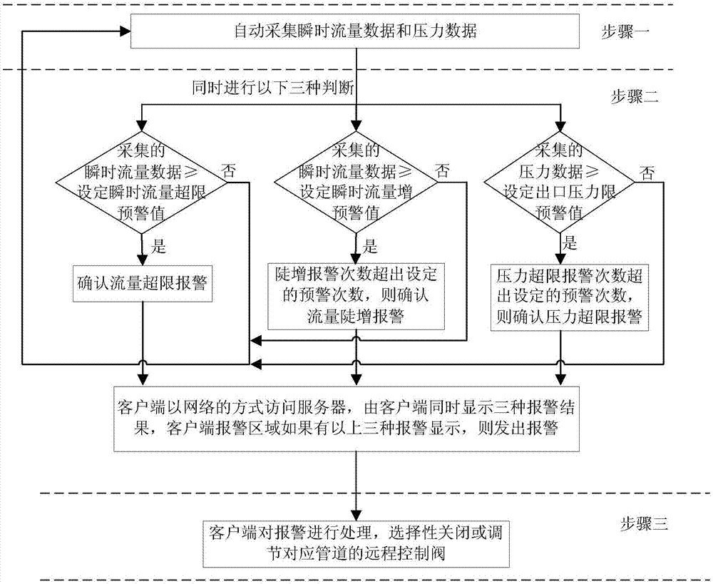
[0064] The alarm unit is used to compare the collected data with the alarm threshold set in the menu unit. If the collected instantaneous flow data is greater than or equal to the alarm value of the device or the collected pressure data is less than or equal to the alarm value of ...
PUM
 Abstract
Description
Claims
Application Information
 - R&D
- Intellectual Property
- Life Sciences
- Materials
- Tech Scout
- Unparalleled Data Quality
- Higher Quality Content
- 60% Fewer Hallucinations
Browse by: Latest US Patents, China's latest patents, Technical Efficacy Thesaurus, Application Domain, Technology Topic, Popular Technical Reports.
© 2025 PatSnap. All rights reserved.Legal|Privacy policy|Modern Slavery Act Transparency Statement|Sitemap|About US| Contact US: help@patsnap.com


