Laboratory test machine

A testing machine and laboratory technology, applied in the direction of optical testing flaws/defects, measuring devices, material analysis through optical means, etc., can solve the problem of inability to meet the imaging and lighting requirements of different products, and the camera angle and height cannot be adjusted , Dimensions cannot be measured, etc., to achieve the effect of simple structure, low maintenance cost and convenient operation

Pending Publication Date: 2017-01-25
SUZHOU DINNAR TECH FOR AUTOMATION CO LTD
View PDF6 Cites 10 Cited by
  • Summary
  • Abstract
  • Description
  • Claims
  • Application Information

AI Technical Summary

Problems solved by technology

With machine vision for quality inspection of products, especially products with smooth and reflective surfaces such as metal products, at present, traditional experimental fixtures can only meet a single type of camera clamping a...

Method used


Image

  • Laboratory test machine
  • Laboratory test machine

Examples


Embodiment 1

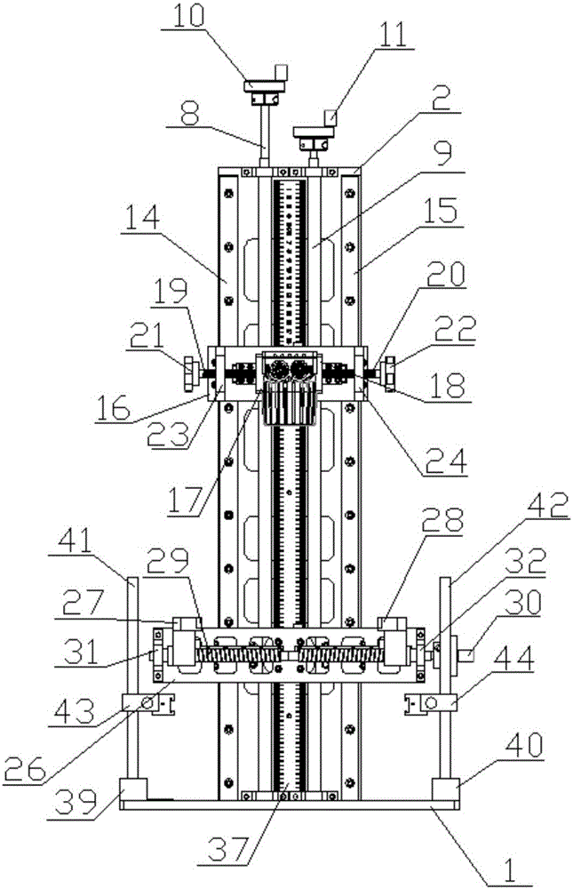
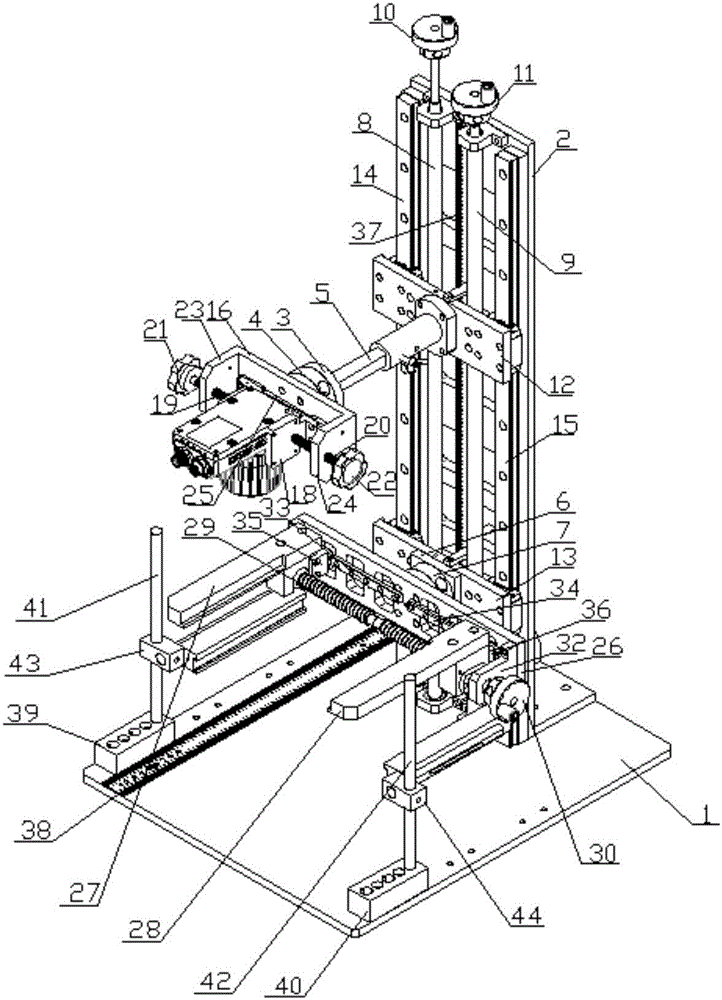
[0025] see figure 1 and 2 Shown, a kind of laboratory test machine platform, it comprises horizontal test platform 1, is located at the support 2 on the horizontal test platform, is located at the camera fixing assembly and the light source fixing assembly with vertical direction freedom degree on the support, described camera The fixing component is arranged above the light source fixing component,

[0026] The camera fixing assembly includes a first rotating mechanism and a first clamping mechanism, and the first rotating mechanism includes a first fixing part 3 and a first rotating part 4 rotationally connected with the first fixing part, and the first fixing part The part is connected to the bracket through the telescopic sleeve 5 arranged horizontally, and the first clamping mechanism is fixed on the first rotating part,

[0027] The light source fixing assembly includes a second rotating mechanism and a second clamping mechanism, the second rotating mechanism includes ...


PUM


Abstract

The invention discloses a laboratory test machine which comprises a horizontal test platform, a bracket arranged on the horizontal test platform and a camera fixing component and a light source fixing component with vertical degree of freedom arranged on the bracket, wherein the camera fixing component is arranged above the light source fixing component and comprises a first rotation mechanism and a first clamping mechanism; the first rotation mechanism comprises a first fixing part and a first rotation part rotatably connected with the first fixing part; the first fixing part is connected with the bracket through a horizontal telescopic sleeve; the first clamping mechanism is fixed on the first rotation part; the light source fixing component comprises a second rotation mechanism and a second clamping mechanism; the second rotation mechanism comprises a second fixing part mounted on the bracket and a second rotation part rotatably connected with the second fixing part; and the second clamping mechanism is fixed on the second rotation part. The laboratory test machine disclosed by the invention is suitable for the mounting fixation and regulation of various cameras and light sources, meets the imaging and lighting requirements of the products different in size and is easy and convenient for assembly/disassembly.

Description

technical field [0001] The invention belongs to the field of machine vision detection, and in particular relates to a laboratory testing machine. Background technique [0002] With the ever-increasing demands for quality and fast production, visual inspection and product identification are becoming more and more important. The reasons are self-evident: reduce the number of non-conforming products and provide qualified products. These requirements are derived from ISO9000 norms or other product liability regulations. Manual visual inspection and product marking are too expensive. It also means unkind, monotonous work. Manufacturing productivity continues to increase and manual inspection is becoming less and less possible. With machine vision for quality inspection of products, especially products with smooth and reflective surfaces such as metal products, at present, traditional experimental fixtures can only meet a single type of camera clamping and the angle and height...

Claims


Application Information

Patent Timeline
IPC IPC(8): G01N21/88G01N21/01
CPCG01N21/01G01N21/88G01N2021/0181
Inventor 秦应化席海强
Owner SUZHOU DINNAR TECH FOR AUTOMATION CO LTD
Why Eureka
Try Eureka