Optical cable laying method for in-situ monitoring of submarine pipelines

A laying method and technology for submarine pipelines, which are applied in optical fiber/cable installation, optics, light guides, etc., can solve the problems of great influence on monitoring distance and accuracy, increase information loss of optical cable, and easy damage to optical cable, so as to avoid monitoring distance and The effect of precision, improving reliability and safety, and avoiding damage to optical cables

Inactive Publication Date: 2017-01-25
NEPTUNE OFFSHORE ENG DEV
View PDF0 Cites 3 Cited by
  • Summary
  • Abstract
  • Description
  • Claims
  • Application Information

AI Technical Summary

Problems solved by technology

At present, the existing laying technology usually adopts three methods. One is to lay the steel pipe first, and then lay the optical cable along the steel pipe laying route. , being squeezed by the stinger and impacted by the water flow, the optical cable is very vulnerable to damage, and the laying survival rate is low; the second is to simply bind or use glue on the water, this method cannot avoid the extrusion damage of the optical cable when it is dragged through the jacket , and in the process of lowering the optical cable with the pipeline, the optical cable may be separated from the sea pipe under the impact of the water flow; the third is to carry out special processing on the sea pipe, and pre-embed thin steel pipes in it as the optical cable passage. This method has defects Because the standard length of the submarine steel pipe is 12m, the optical cable embedded in it needs a joint every 12m, which will greatly increase the information loss in the optical cable and greatly affect the monitoring distance and accuracy.

Method used


Image

  • Optical cable laying method for in-situ monitoring of submarine pipelines
  • Optical cable laying method for in-situ monitoring of submarine pipelines
  • Optical cable laying method for in-situ monitoring of submarine pipelines

Examples


Embodiment Construction

[0026] The present invention will be described in detail below in conjunction with the accompanying drawings and examples.

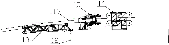
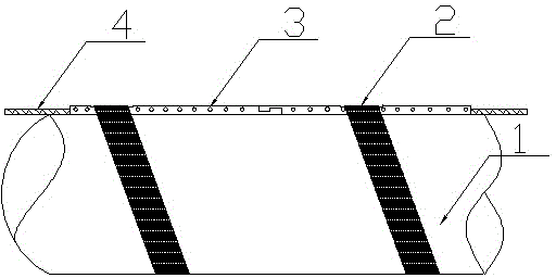
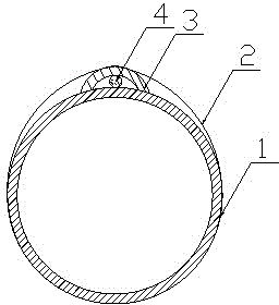
[0027] Such as Figure 1-5 As shown, the present invention is an optical cable laying method for in-situ monitoring of submarine pipelines, and the implementation steps include:

[0028] (1) After the pipe-laying ship 12 is in place, place the take-up and pay-off frame wrapped with the optical cable 4 on the rear side of the stern tensioner 14, and place the cable storage reel wrapped with several sections of optical cable sheath 3 on the take-up and pay-off stand Next, the optical cable fixing device 15 is fixed between the tensioner 14 and the stinger 13, and the steel pipe 1 to be laid is inserted into the center hole of the optical cable fixing device 15 after passing through the tensioner 14;

[0029] (2) Start the optical cable fixing device 15, pull the optical cable 4 and place it on the side of the steel pipe 1, then pull the optical cable shea...


PUM


Abstract

The invention relates to an optical cable laying method for in-situ monitoring of submarine pipeline. A cable jacket with medium exchange holes is adopted, protection of an optical cable in laying and in-situ monitoring is realized, exchange velocity of the internal and external media of the jacket is increased, and monitoring error is lowered; the optical cable is fixed on the water surface, reliability and safety of the optical cable are improved, and cable damage even construction stagnation during underwater operation and ditching by submariners are avoided; through an automatic optical cable fixing device, manual operation during construction is reduced, construction work is lowered, and utilization on weather windows during construction is increased; the entire optical cable is wound continuously, so that impact of an optical cable joint on monitoring distance and accuracy is avoided.

Description

technical field [0001] The invention belongs to the field of submarine pipeline monitoring and integrity management, and in particular relates to an optical cable laying method for in-situ monitoring of submarine pipelines. Background technique [0002] With the rapid development of the offshore oil industry, more and more oil production platforms and submarine pipelines have been put into use. Due to the complicated environment of the submarine pipeline, there is a risk of crude oil leakage during service. Therefore, the submarine pipeline On-site monitoring is a key issue in the oil production industry at present. Optical fiber monitoring, as an essentially explosion-proof, high-sensitivity monitoring technology, is increasingly being used in the monitoring and testing of submarine pipelines. [0003] Optical fiber monitoring is attached to the optical cable laid at the same time as the submarine pipeline, and the optical cable has the characteristics of no compression res...

Claims


Application Information

Patent Timeline
Patent Type & Authority Applications(China)
IPC IPC(8): G02B6/50
CPCG02B6/506
Inventor 王翎羽王鸿轩陈伟
Owner NEPTUNE OFFSHORE ENG DEV
Why Eureka
Try Eureka