Battery system with thermal management

A battery system and heat management technology, applied in secondary batteries, circuits, electrical components, etc., to achieve the effect of reducing liquid leakage and reducing resistance

Active Publication Date: 2019-11-01
TREND POWER TECH CHANGSHU INC
View PDF6 Cites 0 Cited by
  • Summary
  • Abstract
  • Description
  • Claims
  • Application Information

AI Technical Summary

Problems solved by technology

[0006] However, the aforementioned thermal management system still has room for improvement. In view of this, the inventor conducted research and analysis, and developed a new thermal management system for battery modules.

Method used


Image

  • Battery system with thermal management
  • Battery system with thermal management
  • Battery system with thermal management

Examples


Embodiment Construction

[0056] Preferred embodiments of the present invention will be described in detail below in conjunction with the accompanying drawings. Before explaining the present invention, if it is considered that related descriptions of well-known structures or functions may unnecessarily obscure the gist of the present invention, the detailed description thereof will be omitted.

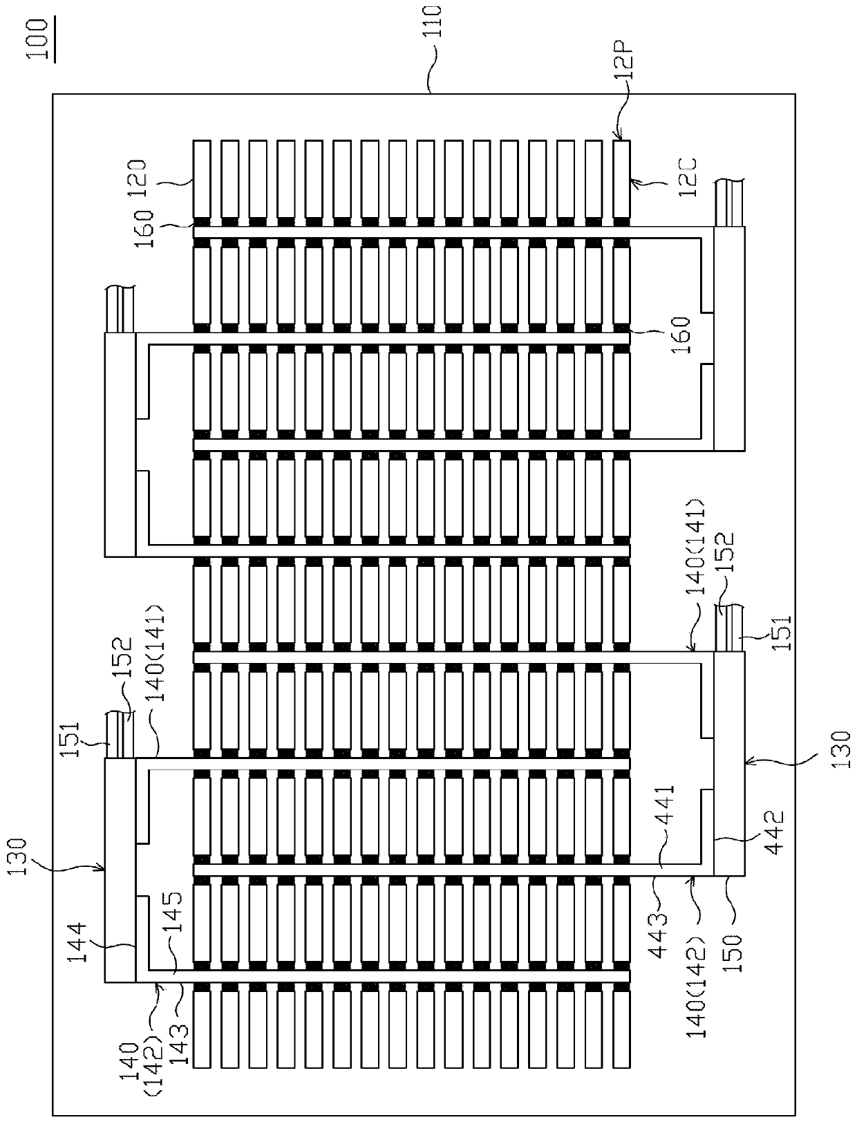
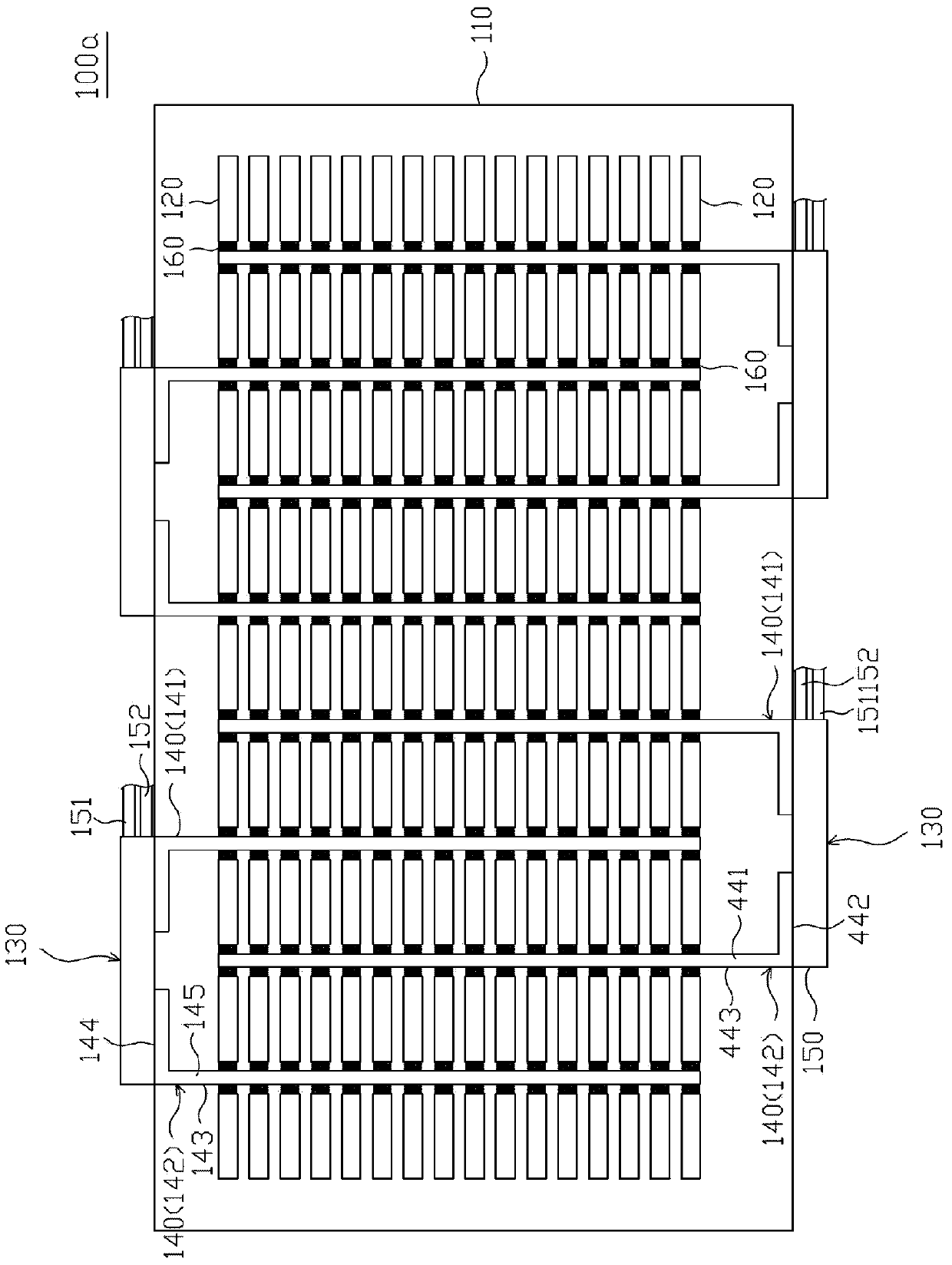
[0057] figure 1 A schematic diagram showing a battery system with thermal management function according to an embodiment of the present invention. Such as figure 1 As shown, the battery system 100 with thermal management function includes a casing 110 , a plurality of battery cells 120 , and at least one regulating unit 130 capable of regulating the surface temperature of the battery cells 120 . The regulating unit 130 and the plurality of battery cells 120 are placed in the casing 110, and the plurality of battery cells 120 are in thermal contact with the regulating unit 130, so that heat can be conducted fr...


PUM


Abstract

The present invention discloses a battery system with a thermal management function, comprising a housing, a plurality of battery cells and at least one temperature control unit. The plurality of battery cells are provided in the housing. The temperature control unit includes at least one heat sink and a liquid heat exchanger. The heat sink comprises a temperature plate, a heat exchange plate and at least one closed chamber. The temperature plate is connected to the heat exchange plate, and the temperature plate extends between the plurality of battery cells to contact the plurality of battery cells, and the working chamber is provided with a working fluid capable of changing the phase between the two phases. The liquid heat exchanger is in thermal contact with the heat exchange plate, wherein a liquid flows through the inside of the liquid heat exchanger for exchanging heat with the heat exchange plate of the liquid and the heat radiating plate.

Description

technical field [0001] The present invention relates to a battery system with thermal management function, in particular to a battery system which applies an active and passive thermal management method to its thermal management function. Background technique [0002] Energy storage systems or electric transportation vehicles include electric vehicles, electric mini-cars, electric boats, electric buses and other vehicles. Under the demand of high power or high discharge rate (Discharge Rate), the battery core will generate electricity during charging and discharging. The chemical exothermic reaction causes thermal runaway of the battery module of the above-mentioned electric vehicle, which further causes the battery to explode or catch fire. [0003] Electric transport vehicles may be used in harsh environments. If the ambient temperature is below zero degrees Celsius, most of the lithium ions in the electrolyte (Electrolyte) inside the battery cells will not be able to move...

Claims


Application Information

Patent Timeline
Patent Type & Authority Patents(China)
IPC IPC(8): H01M10/613H01M10/615H01M10/625H01M10/6555H01M10/6567H01M10/6569
CPCH01M10/613H01M10/615H01M10/625H01M10/6555H01M10/6567H01M10/6569Y02E60/10
Inventor 李炳仁李书琳陈春潮蔡丞阳
Owner TREND POWER TECH CHANGSHU INC
Why Eureka
Try Eureka