Full network flow monitoring method

A network traffic and network monitoring technology, applied in the field of information security, can solve problems such as not being well applicable to the whole network big data monitoring, increasing flow coverage, increasing router monitoring redundancy, etc.

Active Publication Date: 2017-01-25
中国人民解放军防空兵学院
View PDF6 Cites 3 Cited by
  • Summary
  • Abstract
  • Description
  • Claims
  • Application Information

AI Technical Summary

Problems solved by technology

[0003] The existing technology also conducts some improved research on the above-mentioned router sampling, but the current improvement method only focuses on the improvement of the solution of a single router, and is still not suitable for the monitoring of big data in the whole network.
In addition, these improved methods lack

Method used


Image

  • Full network flow monitoring method
  • Full network flow monitoring method
  • Full network flow monitoring method

Examples


Embodiment 2

[0115] The difference between this embodiment and Embodiment 1 is that the above sampling list can also be calculated using the directed graph method to solve the edge E of the OD flow to the router 3 , the solution method is as follows: It is known to transform the entire network into a directed graph G, where V represents a node, and E represents an edge connecting each node;

[0116] V={source,sink}∪{OD i} 1≤i≤m ∪{R j} 1≤j≤n , where source represents the source point and sink represents the sink point;

[0117] E=E 1 ∪E 2 ∪E 3 , where E 1 Indicates the edge from the source point to the OD flow, E 2 represents the edge from the router to the sink, E 3 Indicates the edge of the OD flow to the router;

[0118] { E 1 = { ( s o u r c e , OD ...


PUM


Abstract

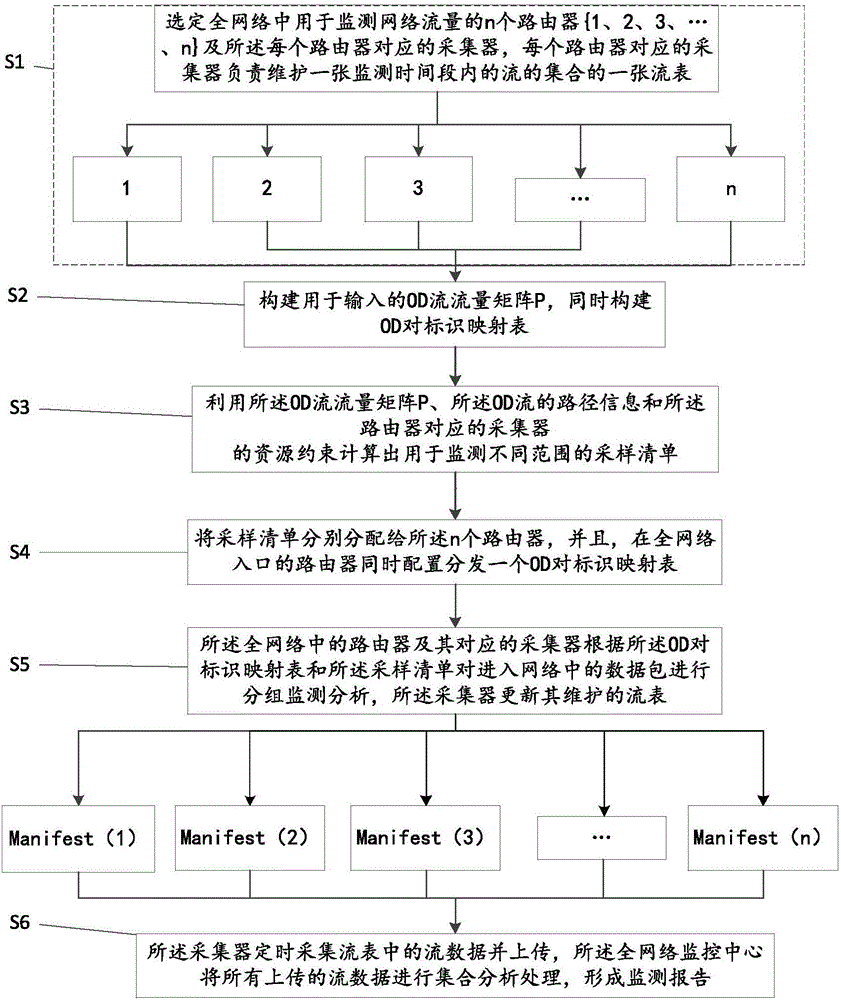
The invention discloses a full network flow monitoring method which comprises the following steps: (1) selecting routers and collectors for monitoring the flow in a full network; (2) acquiring m OD flows, extracting path information of the OD flows to construct an OD flow matrix P, and encoding the OD flows to form an OD pair identity mapping table; (3) computing sampling lists in different ranges by use of the OD flow matrix, the path information of the OD flows, and the resource constraint of the routers; (4) distributing the sampling lists to the routers, and distributing the OD pair identity mapping table while entering the router; (5) enabling the routers and the collectors thereof to monitor a data packet according to the OD pair identity mapping table and the sampling lists so as to update flow data in the collector flow table; and (6) enabling the collectors to collect and upload the flow data to form a monitoring report. Through the adoption of the monitoring method disclosed by the invention, a large number of redundancy cannot be produced between the routers, the communication between the collectors is unnecessary, and the monitoring method has the advantages of being small in network burden, large in full network coverage rate and high in processing efficiency.

Description

technical field [0001] The invention relates to the technical field of information security, in particular to a monitoring method for the entire network flow. Background technique [0002] In the prior art, network traffic monitoring relies on the number of flows at all levels collected on routers, but the monitoring capability of each router is limited, and network operators want to use the best way possible to utilize router monitoring capabilities. However, existing routers operate individually, and each router independently records the traffic it monitors. Not only does this approach not utilize router resources efficiently, but it also increases the network operator's impact on handling redundancy and data ambiguity due to multiple router monitoring. From a single point of view, the monitoring method in the prior art cannot achieve the purpose of directly specifying and realizing the whole network measurement by the network operator. And there is a primitive disconne...

Claims


Application Information

Patent Timeline
IPC IPC(8): H04L12/26H04L12/771H04L45/60
CPCH04L43/04H04L43/06H04L43/08H04L43/50H04L45/60
Inventor 钱叶魁刘凤荣龚雁辉赵鑫张兆光邹富春杜江黄浩蒋文峰李宇翀王丙坤杨瑞朋夏军波
Owner 中国人民解放军防空兵学院
Why Eureka
Try Eureka