Oil drill rod circumferential surface rust removing device

An oil drill pipe and circumferential surface technology, which is applied to grinding drive devices, machine tools designed for grinding workpiece rotating surfaces, and grinding machines, etc., can solve the problems of low efficiency, inability to grind, and high operating intensity of construction personnel, and achieve high efficiency. High and fast installation effect

Active Publication Date: 2017-02-01
江苏省德诚测控设备有限公司 +1
View PDF6 Cites 29 Cited by
  • Summary
  • Abstract
  • Description
  • Claims
  • Application Information

AI Technical Summary

Problems solved by technology

After use, the surface of the oil drill pipe will form a dirt layer and rust layer. During equipment maintenance, the oil drill pipe needs to remove the dirt layer and rust layer on the surface. The operation of the prior art is to use a manual hand-held grinder for grinding. To remove the dirt layer and rust layer, this method has the following disadvantages, the construction period is long, the construction personnel's operation intensity is high, and the efficiency is extremely low. Therefore, how to replace this traditional grinding method has become an urgent problem for those skilled in the art and technicians. question
[0003] In a kind of oil drill pipe surface derusting device whose notification number is CN205363514U, the sandpaper to be polished is arranged on four ring-shaped holding plates respectively, and the four holding plates form a complete ring and the outer circumferential surface of the drill pipe is Completely cover, and then move the device in parallel to make sandpaper on the surface of the drill pipe for grinding and rust removal. Compared with the traditional rust removal method, the above-mentioned documents have obviously improved the efficiency, but there are some defects in it as follows: 1. The diameter of the drill pipe is different. , the drill pipe with a small diameter cannot be in contact with the sandpaper and cannot be polished. For the drill pipe with a large diameter, the holding plate will be stretched, and there will be a gap between the holding plates, and the annular plate will move along the axial direction of the drill pipe. The surface of the drill pipe at this gap cannot be polished by sandpaper; 2. The structure is complex, which makes the installation process of the drill pipe cumbersome; 3. The efficiency of rust removal is low, and the sandpaper needs to be moved many times to remove the rust layer of the basic structure

Method used


Image

  • Oil drill rod circumferential surface rust removing device
  • Oil drill rod circumferential surface rust removing device
  • Oil drill rod circumferential surface rust removing device

Examples


Embodiment 1

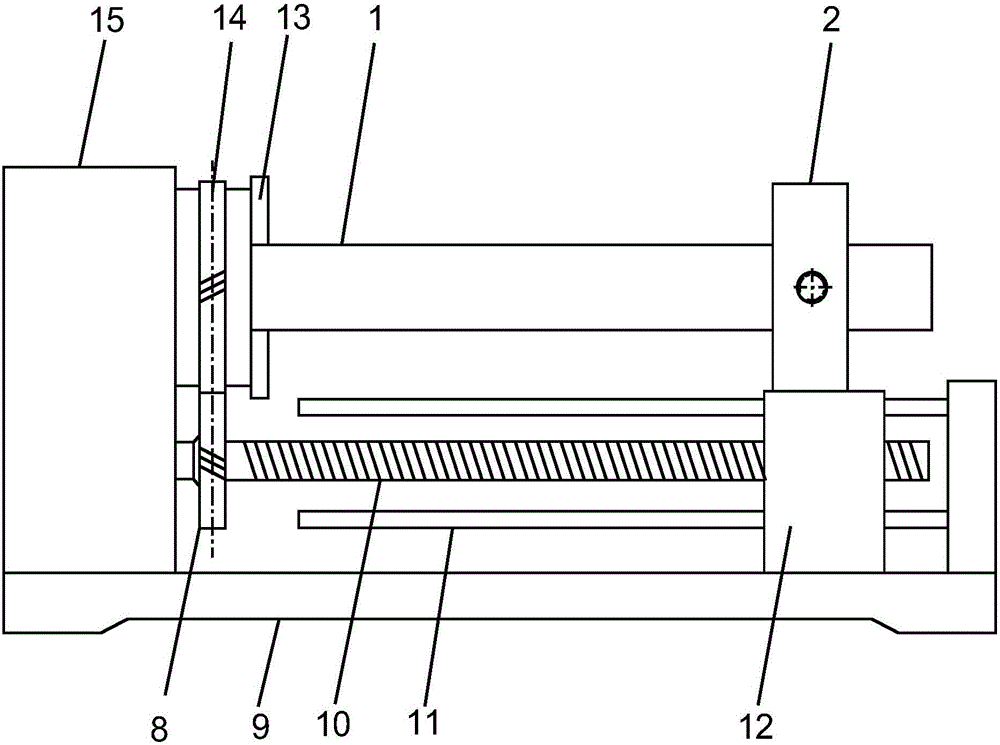
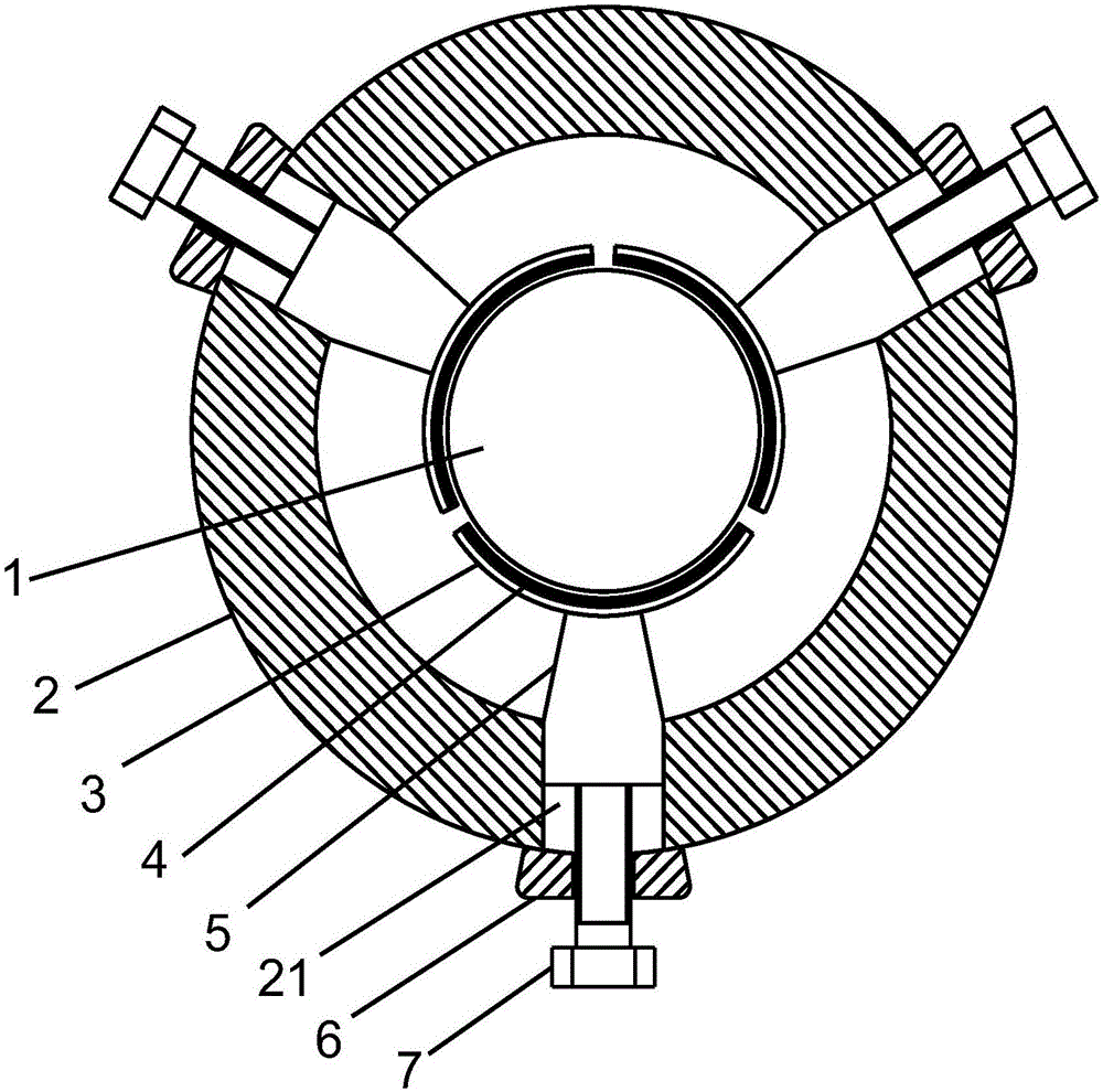
[0018] see Figure 1~2 , in the embodiment of the present invention, a kind of oil drill pipe circumferential surface derusting device comprises: frame 9, power box 15, three-jaw chuck 13 and annular plate 2, described power box 15 and existing common lathe The power box is similar, and includes a power assembly composed of a driving device (motor) and a speed change mechanism. The three-jaw chuck 13 is connected to the driving device, and the annular plate 2 is a ring-shaped plate, and a holding plate is arranged inside it. 3. The holding plate 3 is three arc-shaped plates formed by dividing the entire annular plate into three equal parts. The inner surface of the holding plate 3 is provided with sandpaper 4, and the holding plate 3 is wrapped on the circumferential surface of the drill pipe 1. The middle part of the outer surface of the plate 3 is welded to connect the slide block 5, and three equally divided cylindrical holes 21 are arranged on the annular plate 2, and the ...

Embodiment 2

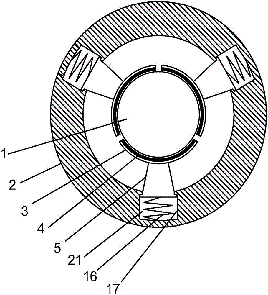
[0020] see Figure 3-4 , the present invention provides another embodiment, the bolt 7 and boss 6 in Embodiment 1 are replaced, and a compression spring 16 is set in the cylindrical hole 21. When the drill pipe 1 is installed, the compression spring 16 is compressed, and the The elastic force of the spring 16 makes the grinding sandpaper 4 close to the surface of the drill rod 1, a limit groove 17 is set in the cylindrical hole 21, a protrusion is arranged on the slider 5 and is located in the limit groove 21, and the limit groove 17 limits the movement of the slider 5. Move to prevent the slide block 5 from breaking away from the cylindrical hole 21; the expansion plate 18 is also fixed and inclined on the holding plate 3, and the three expansion plates 18 can encircle a trumpet-shaped variable diameter hole. When the drill pipe 1 is installed, from the expansion The large round hole end of the diameter plate 18 penetrates, and the drill pipe 1 contacts with the expansion pla...


PUM


Abstract

The invention discloses an oil drill rod circumferential surface dust removing device which comprises a machine frame, a power box, a three-jaw chuck and an annular plate. Holding plates are arranged in the annular plate. The holding plates are three arc plates which are formed after the whole annular plate is equally divided into three parts. The inner surface of each holding plate is provided with polishing abrasive paper. The middle of the outer surface of each holding plate is connected with a sliding block in a welded mode. The annular plates are provided with three equally-divided cylindrical holes. The sliding blocks are arranged in the cylindrical holes. Bosses are fixedly arranged outside the cylindrical holes. First thread holes are formed in the bosses. Bolts are arranged in the first thread holes. The annular plates are fixed to a sliding base in a welded mode. The sliding base is arranged on the machine frame and can move on the machine frame in parallel. The sliding base is provided with a second thread hole. A screw rod is arranged in the second thread hole. A screw rod is arranged in the second thread hole. A gear is connected to the left end of the screw rod. The outer circumference of the three-jaw chuck is provided with an annular rack. The rack is engaged with the gear. According to the oil drill rod circumferential surface dust removing device, the polishing strength can be adjusted, it is ensured that dust on the surface of a drill rod is thoroughly removed, and the efficiency is higher.

Description

technical field [0001] The invention relates to the field of petroleum equipment, in particular to a rust removal device for the peripheral surface of petroleum drill pipes. Background technique [0002] Oil drill pipe is an indispensable and important tool in oil drilling operations. After use, the surface of the oil drill pipe will form a dirt layer and rust layer. During equipment maintenance, the oil drill pipe needs to remove the dirt layer and rust layer on the surface. The operation of the prior art is to use a manual hand-held grinder for grinding. To remove the dirt layer and rust layer, this method has the following disadvantages, the construction period is long, the construction personnel's operation intensity is high, and the efficiency is extremely low. Therefore, how to replace this traditional grinding method has become an urgent problem for those skilled in the art and technicians. question. [0003] In a kind of oil drill pipe surface derusting device whos...

Claims


Application Information

Patent Timeline
Patent Type & Authority Applications(China)
IPC IPC(8): B24B27/033B24B5/04B24B5/35B24B41/02B24B47/04
CPCB24B5/04B24B5/35B24B27/033B24B41/02B24B47/04
Inventor 不公告发明人
Owner 江苏省德诚测控设备有限公司
Why Eureka
Try Eureka