Unmanned plane fueling vehicle and working method thereof

A technology for unmanned aerial vehicles and refueling vehicles, which is applied in the direction of oil tankers, motor vehicles, and goods transport vehicles, etc., and can solve the problems of long refueling time, inapplicability, and low battery life.

Active Publication Date: 2017-02-01
AEROSUN CORP
View PDF8 Cites 2 Cited by
  • Summary
  • Abstract
  • Description
  • Claims
  • Application Information

AI Technical Summary

Problems solved by technology

With the in-depth advancement of mechanization and information construction, the demand for domestic drones is growing rapidly, and the variety and quantity of drones will also increase. The application range of drones has involved many fields, but most drones are Facing the problem of low battery life, gasoline-powered drones will provide longer battery life. In order to maximize the use of fuel load capacity and platform durability, the use of lightweight materials will undoubtedly increase the flight life of drones. At the same time, drones generally use soft fuel bladders
[0003] At present, in the field of UAVs, manual or electric fuel pumps are generally used to refuel UAVs. The above-mentioned refueling methods have the following problems: it is difficult to control the amount of fuel to be refilled and the refilling time is long. Note or electric fuel pump refilling is suitable for model aircraft and small UAVs, but not for medium or large UAVs, especially for UAVs with high safety requirements such as soft fuel bladders.

Method used


Image

  • Unmanned plane fueling vehicle and working method thereof
  • Unmanned plane fueling vehicle and working method thereof
  • Unmanned plane fueling vehicle and working method thereof

Examples


Embodiment Construction

[0094] The present invention will be described in detail below in conjunction with the accompanying drawings and embodiments.

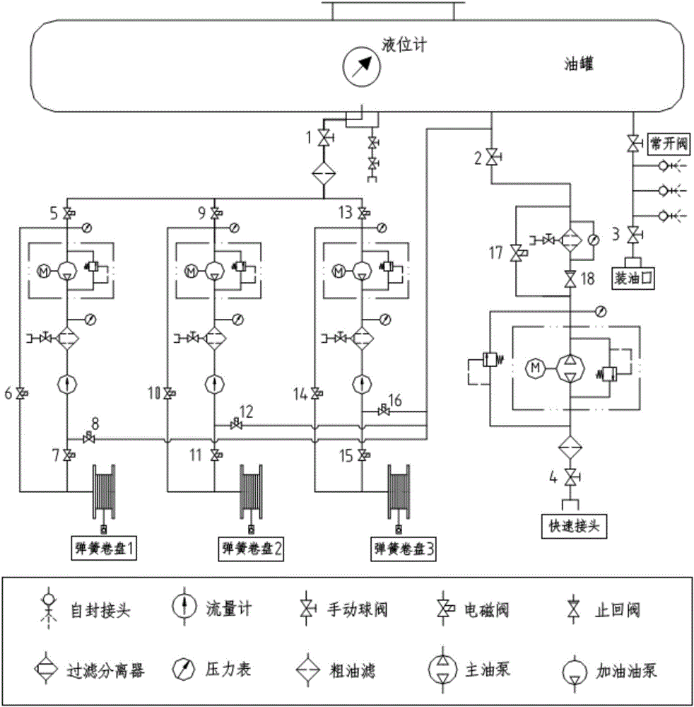
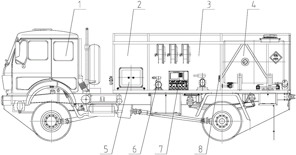
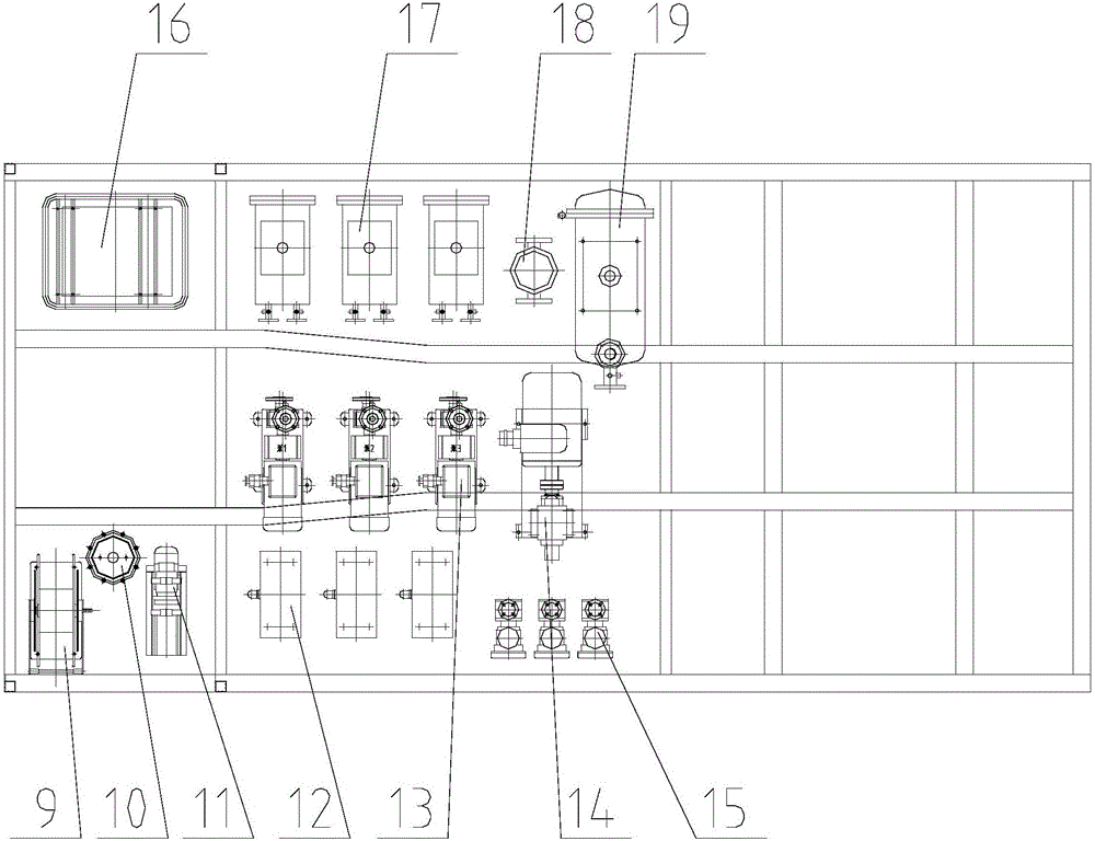
[0095] An unmanned aerial vehicle refueling vehicle of the present invention comprises a vehicle body, and the chassis 1 of the vehicle body is provided with an accessory cabin 2, an operating cabin 3 and an oil tank assembly 4; the accessory cabin 2 is provided with a power assembly 5, the inside of the operating cabin 3 is provided with an oil circuit system 6, an electrical system 7 and an air circuit system 8; the oil circuit system 6 includes three groups of fuel oil circuits and one group of main oil circuits; The first manual ball valve 20 connected to the oil tank, the first manual ball valve 20 is connected to a coarse filter, and the coarse filter is respectively connected to the first solenoid valve 24, the fifth solenoid valve 28 and the ninth solenoid valve 32; A solenoid valve 24 is sequentially connected to the fuel pump, filter separat...


PUM


Abstract

The invention discloses an unmanned plane fueling vehicle and a working method thereof. The unmanned plane fueling vehicle comprises a vehicle body. An accessory bin, an operation bin and an oil tank assembly are arranged on a chassis of the vehicle body. A power assembly is arranged in the accessory bin. An oil circuit system, an electric system and a gas circuit system are arranged in the operation bin. The oil circuit system comprises three sets of fueling circuits and a main oil circuit. Each fueling circuit comprises a first manual ball valve connected with an oil tank. Each first manual ball valve is connected with a coarse filter. The coarse filter is connected with a first electromagnetic valve, a fifth electromagnetic valve and a ninth electromagnetic valve. According to the unmanned plane fueling vehicle and the working method thereof, functions and technologies are advanced, operation is easy, performance is reliable, a soft oil bag can be effectively protected in oil fueling and pumping processes, and the situations that the oil bag is damaged during fueling, or oil in the oil bag cannot be pumped completely during oil pumping, and consequently the service life of the oil bag is shortened are avoided. The unmanned plane fueling vehicle can also be applied to other fields that fuel is stored in soft oil bags and safety requirements are extremely high.

Description

technical field [0001] The invention relates to a UAV refueling vehicle, in particular to the field of refueling technology for UAVs using soft oil bags for fuel storage and high safety requirements, and is mainly used for refueling or extracting fuel for UAVs on site; The invention also relates to a working method of the drone refueling vehicle. Background technique [0002] In recent years, the drone industry at home and abroad has developed rapidly, but the current application level of drones in my country is only in its infancy, which also means that the domestic drone market has a huge room for future development. With the in-depth advancement of mechanization and information construction, the demand for domestic drones is growing rapidly, and the variety and quantity of drones will also increase. The application range of drones has involved many fields, but most drones are Facing the problem of low battery life, gasoline-powered drones will provide longer battery li...

Claims


Application Information

Patent Timeline
Patent Type & Authority Applications(China)
IPC IPC(8): B64F1/28B60P3/22
CPCB60P3/224B64F1/28
Inventor 夏友权王士晋方俊蕾李绍锋唐震
Owner AEROSUN CORP
Why Eureka
Try Eureka