
Waste cable collecting device

A cable take-up device and cable technology, used in cable installation devices, cable installation, equipment for cutting/splitting cables, etc., can solve the problems of different sizes of cable groups, difficult placement, inaccurate weighing values, etc.

Inactive Publication Date: 2017-02-01
董高正
View PDF0 Cites 2 Cited by
  • Summary
  • Abstract
  • Description
  • Claims
  • Application Information

AI Technical Summary

Problems solved by technology

In this way, the recovered cable clusters are of different sizes and shapes, which is not only not conducive to inventory by warehouse personnel, but also not conducive to storage.
Since waste cables are measured by weight, they need to be weighed and stored in pieces after recycling. The above-mentioned cable clusters are not easy to take and place when weighing, and it is even more difficult to place them, which makes weighing difficult. Due to the large size of the cable clusters, it is easy to scatter Inaccurate weighing value and low efficiency

Method used


Image

  • Waste cable collecting device
  • Waste cable collecting device
  • Waste cable collecting device

Examples


Embodiment Construction

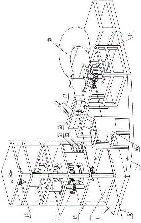
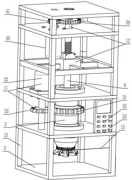
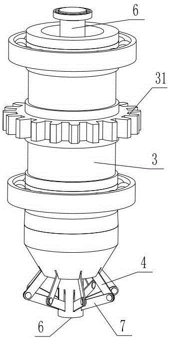
[0030] As shown in the figure, the waste cable take-up device includes a base 14 on which a weighing instrument 1 is fixed, a main frame 13 is installed on the weighing platform 2 of the weighing instrument, and a rotating sleeve 3 arranged axially and vertically is rotatably installed on the main frame. The outer wall of the sleeve is in the shape of a cone with a thin lower end and a thick upper end. The lower uniform ring of the sleeve is provided with a swing arm 4 articulated by a horizontal hinge shaft 5. A central shaft 6 is inserted axially in the sleeve, and the lower end ring of the central shaft is provided with a pendulum The arms correspond to the support arm 7, the lower end of the support arm is hinged with the central axis, and the upper end of the support arm is hinged with the corresponding lower end of the swing arm. When the central axis slides up to the upper stroke point, the support arm is set perpendicular to the central axis, and the lower end of the swin...


PUM


Abstract

The invention discloses a waste cable collecting device which comprises a base which is fixedly provided with a weighing instrument, a main power device, a lifting device, a cutting device and a starting and stopping device; a main frame is installed on a weighing table of the weighing instrument and is rotationally provided with a rotary sleeve; the outer wall of the rotary sleeve is in a conical shape with thinner lower end and thicker upper end; swing arms which are hinged to the lower part of the rotary sleeve through horizontal hinge shafts respectively are uniformly arranged at the lower part of the rotary sleeve annularly; a center shaft is axially inserted into the rotary sleeve in a sliding manner; supporting arms are annularly arranged at the lower part of the center shaft; the lower end of each supporting arm is hinged to the center shaft; the upper end of each supporting arm is hinged to the lower end of the corresponding swing arm; when the center shaft slides upward to an up stroke point, the supporting arms are perpendicular to the center shaft, and the lower end of each swing arm is farther away from the center shaft than the upper end of each swing arm; and when the center shaft slides downward to a down stroke point, the upper end of each swing arm is farther away from the center shaft than the two ends of the corresponding supporting arm both, and the lower end of each swing arm is arranged on the outer side of a connecting line of the upper end of each swing arm and the lower end of the corresponding supporting arm. The waste cable collecting device can automatically enable a waste cable to be wound in bundles and is compact in bundle, liable in bundling up, high in automation degree with automatic accurate weighing and automatic material throwing and simple in operation with capability of operation by one person.

Description

Technical field [0001] The invention relates to a waste cable take-up device. Background technique [0002] The wire and cable products used in the power system mainly include overhead bare wires, busbars (bus bars), power cables (plastic cables, oil-paper cables (basically replaced by plastic power cables), rubber cables, overhead insulated cables), branch cables (Replace part of the bus), electromagnetic wires, and electrical equipment wires and cables for power equipment. Many common faults occur during use of power cables, such as mechanical damage, insulation damage, insulation moisture, insulation deterioration, overvoltage, and cable overheating faults. When the above-mentioned fault occurs in the line, the power supply of the faulty cable should be cut off, the fault point should be found, the fault should be checked and analyzed, and then repair and test should be carried out. When the power cable runs for a long time, the above-mentioned faults will become more and mo...

Claims


Application Information

Patent Timeline
Patent Type & Authority Applications(China)
IPC IPC(8): B65B63/04B65B27/06H02G1/00
CPCB65B63/04B65B27/06H02G1/005
Inventor 董高正
Owner 董高正
Learn More