High-efficiency kit

A reagent kit and high-efficiency technology, applied in rigid containers, clamping devices, parts of bottles/cans, etc., can solve the problems of easy sliding or falling off of racks and reagent tubes, inability to meet requirements, time-consuming and labor-intensive, etc., to achieve isolation The effects of external pollution, space saving and wide application

Inactive Publication Date: 2017-02-01
TIANJIN MINGHENG TECH DEV
View PDF0 Cites 10 Cited by
  • Summary
  • Abstract
  • Description
  • Claims
  • Application Information

AI Technical Summary

Problems solved by technology

[0002] With the development of science and technology, biotechnology is also developing rapidly. Not only medical institutions involve the use of biological reagents, but many scientific research institutes and schools use biological reagents in teaching and research, and even many companies now have their own The research and development department of the company will also use biological reagents. It can be seen that biological reagents are widely used now, and more and more high-efficiency kits are used. Since most high-efficiency kits store biological reagents, many biological reagents require Its activity can only be guaranteed at a specific temperature, so it is required that the high-efficiency reagent kit can provide a good storage environment, and at present, in order to distinguish multiple reagents, reagent tubes of multiple specifications are generally used, and the reagent tubes are placed in the high-efficiency reagent In the box, they are all placed on the stand. When moving the high-efficiency reagent box, the stand and the reagent tube are easy to slide or fall off, causing the reagent to spill. In addition, reagent bottles of multiple specifications need multiple stands of different specifications. Fixed, different specifications of the racks are time-consuming and laborious in the production process, and at the same time cannot meet the needs of the market

Method used


Image

  • High-efficiency kit
  • High-efficiency kit

Examples


Embodiment Construction

[0024] It should be noted that, in the case of no conflict, the embodiments of the present invention and the features in the embodiments can be combined with each other.

[0025] In describing the present invention, it should be understood that the terms "center", "longitudinal", "transverse", "upper", "lower", "front", "rear", "left", "right", " The orientations or positional relationships indicated by "vertical", "horizontal", "top", "bottom", "inner" and "outer" are based on the orientations or positional relationships shown in the drawings, and are only for the convenience of describing the present invention and Simplified descriptions, rather than indicating or implying that the device or element referred to must have a particular orientation, be constructed and operate in a particular orientation, and thus should not be construed as limiting the invention. In addition, the terms "first", "second", etc. are used for descriptive purposes only, and should not be understood ...


PUM


Abstract

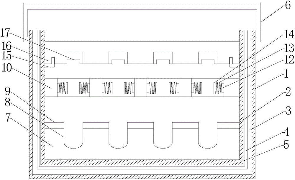
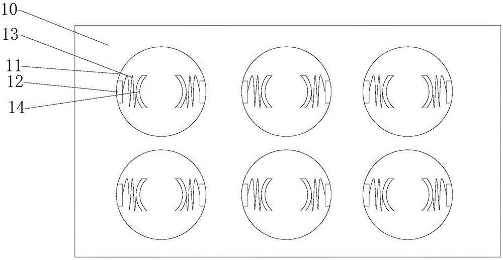
The invention provides a high-efficiency kit which comprises a kit lid and a kit body. The kit lid is located on the kit body. A supporting plate, a corrosion resisting plate, a clamping plate and a cover plate are arranged in the kit body. The supporting plate is located at the bottom of the inner side of the kit body. A plurality of tube grooves are formed in the supporting plate. The corrosion resisting plate is fixed to the supporting plate. A plurality of through holes corresponding to the positions of the tube grooves are formed in the corrosion resisting plate. The hole diameter of the through holes is identical to the diameter of the tube grooves. The clamping plate is located above the corrosion resisting plate. The high-efficiency kit is provided with a clamping mechanism. Elastic pieces are arranged in the clamping mechanism. The clamping mechanism can contain reagent tubes of different specifications through contraction of the elastic pieces, the application range is wide, and the space is saved. The cover plate can achieve the function of isolating outside pollution while fixing the reagent tubes.

Description

technical field [0001] The invention belongs to the field of biology, and in particular relates to a high-efficiency kit. Background technique [0002] With the development of science and technology, biotechnology is also developing rapidly. Not only medical institutions involve the use of biological reagents, but many scientific research institutes and schools use biological reagents in teaching and research, and even many companies now have their own The research and development department of the company will also use biological reagents. It can be seen that biological reagents are widely used now, and more and more high-efficiency kits are used. Since most high-efficiency kits store biological reagents, many biological reagents require Its activity can only be guaranteed at a specific temperature, so it is required that the high-efficiency reagent kit can provide a good storage environment, and at present, in order to distinguish multiple reagents, reagent tubes of multip...

Claims


Application Information

Patent Timeline
Patent Type & Authority Applications(China)
IPC IPC(8): B65D25/04B65D25/10B65D25/14B65D45/02
CPCB65D25/04B65D25/105B65D25/14B65D45/02
Inventor 王盛楠
Owner TIANJIN MINGHENG TECH DEV
Why Eureka
Try Eureka