Aeration reaction device of chlorine dioxide gas

A chlorine dioxide and reaction device technology, applied in chlorine dioxide, chlorine oxide and other directions, can solve the problem of low purity of chlorine dioxide, and achieve the effect of sufficient reaction and high purity

Inactive Publication Date: 2017-02-01
吴予奇 +2
5 Cites 0 Cited by

AI-Extracted Technical Summary

Problems solved by technology

[0005] The main purpose of the present invention is to provide an aeration reaction device for chlorine dioxide gas, which aim...

Method used

Further, in order to facilitate the premixed raw material overflows in the first aeration reaction chamber 121 from the liquid outlet 112, simultaneously, the raw material after mixing enters the aeration reaction chamber group 12 and carries out stepwise multistage aeration reaction, which helps the overall process linkage effect to improve the purity of chlorine dioxide gas. The aeration reaction chamber includes the first aeration reaction chamber 121, the second aeration reaction chamber 122 and the The third aeration reaction chamber 123; the feed port 1212 of the first aeration reaction chamber 121 is connected with the liquid outlet 112 of the raw material premixing chamber 11, and the height of the liquid outlet 112 of the raw material premixing chamber 11 is higher than that of the first aeration chamber. The height of the feed port 1212 of the gas reaction chamber 121.
In addition, referring to Table 3, it is also possible to further improve the purity of chlorine dioxide gas by controlling the ratio of raw materials and the speed at which raw materials enter the aeration reaction chamber group 12. Specifically, the speed at which raw materials enter the aeration reaction chamber group 12 refers to how long the raw materials stay in the aeration reaction chamber group 12 for reaction and are completely blown off by aeration.
The aeration reaction device of the chlorine dioxide gas that the embodiment of the present invention provides, by making a synthetic device that produces chlorine dioxide gas, chlorine dioxide ga...

Abstract

The invention belongs to the field of the chlorine dioxide synthesis technology and provides an aeration reaction device of chlorine dioxide gas. The aeration reaction device comprises an aeration reaction bin set. The aeration reaction bin set comprises multiple aeration reaction bins sequentially connected according to a raw material treatment path, and the volumes of the aeration reaction bins are sequentially reduced. Each aeration reaction bin is provided with a feed port, a discharge port, an aeration opening and a chlorine dioxide gas overflow opening. An aeration block for quantitative aeration is arranged in each aeration reaction bin. The aeration reaction bin set with the volumes sequentially reduced is arranged, so that when raw materials of chlorine dioxide are converted, the purity of the generated chlorine dioxide gas is high, chlorine dioxide has no side effects when exerting effects, and environmental protection is promoted.

Application Domain

Chlorine dioxide

Technology Topic

ChemistryRaw material +2

Image

  • Aeration reaction device of chlorine dioxide gas
  • Aeration reaction device of chlorine dioxide gas
  • Aeration reaction device of chlorine dioxide gas

Examples

  • Experimental program(1)

Example Embodiment

[0021] In order to make the objectives, technical solutions and advantages of the present invention clearer, the following further describes the present invention in detail with reference to the accompanying drawings and embodiments. It should be understood that the specific embodiments described here are only used to explain the present invention, but not to limit the present invention.
[0022] It should be noted that when an element is referred to as being "fixed to" or "disposed on" another element, it can be directly on the other element or indirectly on the other element. When an element is referred to as being "connected to" another element, it can be directly connected to the other element or indirectly connected to the other element.
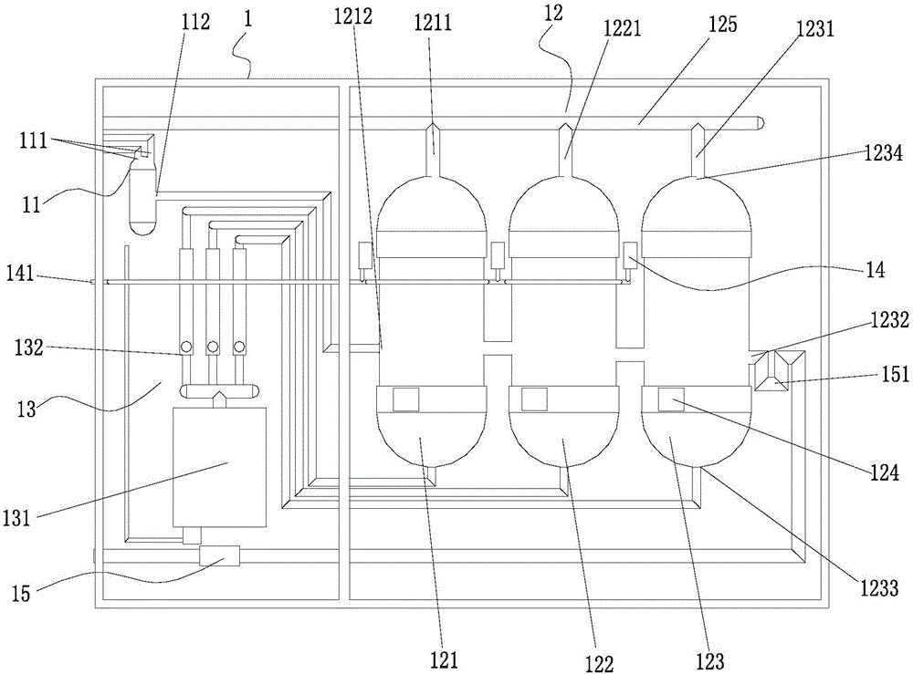
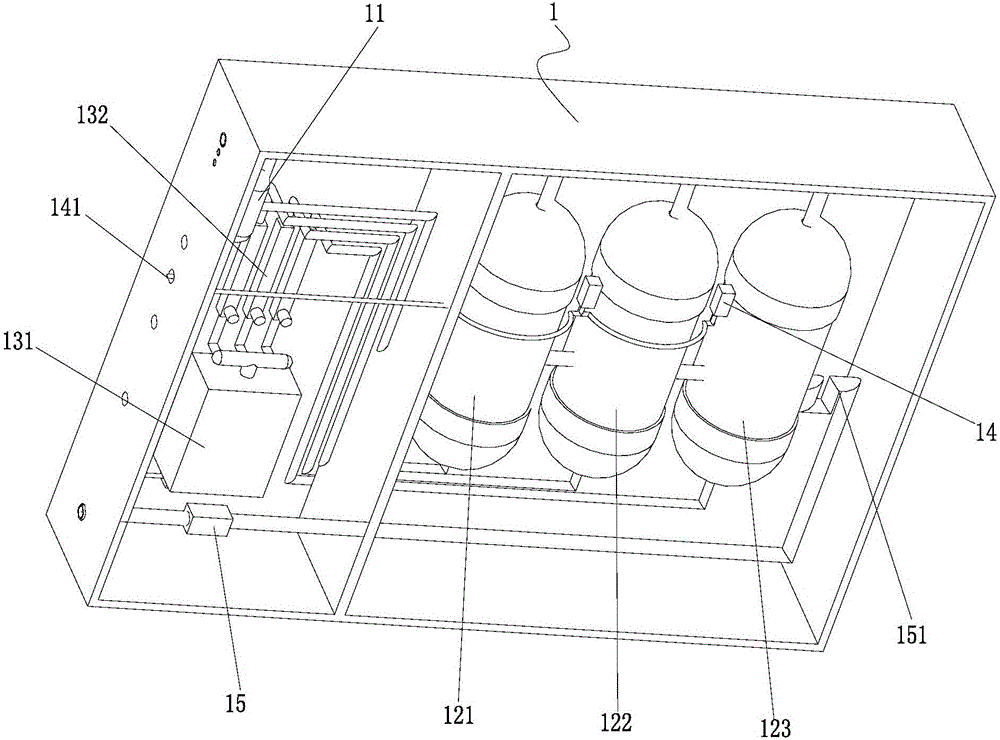
[0023] The present invention provides an aeration reaction device for chlorine dioxide gas. The aeration reaction chamber group 12 arranged in sequence according to the raw material processing path and the volume is sequentially reduced, so that the purity of the chlorine dioxide gas produced is high, so that Chlorine dioxide has no side effects while exerting its effects, which is beneficial to environmental protection.
[0024] See attached figure 1 with figure 2 The aeration reaction device for chlorine dioxide gas includes an aeration reaction chamber group 12; the aeration reaction chamber group 12 includes a plurality of aeration reaction chambers that are sequentially connected according to a raw material processing path and have successively decreasing volumes; Each aeration reaction chamber is provided with a feed port 1212, a discharge port 1232, an aeration port 1233, and a chlorine dioxide gas overflow port 1234, and each aeration reaction chamber is provided with an aeration block 124 for quantitative aeration.
[0025] The aeration reaction device for chlorine dioxide gas provided by the embodiment of the present invention is to produce a synthesis device for generating chlorine dioxide gas. When the chlorine dioxide gas is synthesized, the raw materials enter the aeration reaction of decreasing volume through the feed port 111 The warehouse group 12 performs multi-stage aeration reaction, so that the process linkage function occurs in the aeration reaction warehouse group 12, and the chlorine dioxide raw material reacts more fully during the conversion process, so that the purity of the chlorine dioxide gas produced Achieve extremely high, so that chlorine dioxide has no side effects while exerting its effects, which is beneficial to environmental protection.
[0026] In addition, before the synthesis of chlorine dioxide gas, preferably, the raw material pre-mixing bin 11 can also be set so that the raw materials are first mixed in the raw material pre-mixing bin 11, and the mixed raw materials enter the aeration reaction bin group 12 for more processing. The stage aeration reaction further helps the chlorine dioxide gas react more fully to improve the purity of the chlorine dioxide gas.
[0027] Further, in order to facilitate the overflow of the pre-mixed raw materials from the liquid outlet 112 into the first aeration reaction chamber 121, at the same time, the mixed raw materials enter the aeration reaction chamber group 12 for stepwise multi-stage aeration reaction. Contribute to the overall generation of process linkages to improve the purity of chlorine dioxide gas. The aeration reaction chamber includes a first aeration reaction chamber 121, a second aeration reaction chamber 122, and a third aeration reaction chamber that are sequentially connected and have decreasing volumes. Aeration reaction chamber 123; the feed inlet 1212 of the first aeration reaction chamber 121 is connected to the liquid outlet 112 of the raw material premixing chamber 11, and the height of the liquid outlet 112 of the raw material premixing chamber 11 is higher than that of the first aeration reaction chamber 121 the height of the inlet 1212.
[0028] In addition, the height of the inlet 1212 of the first aeration reaction chamber 121 is higher than the height of the outlet 1232, and the height of the inlet 1212 of the second aeration reaction chamber 122 is higher than the height of the outlet 1232. The height of the inlet 1212 of the third aeration reaction chamber 123 is higher than the height of the outlet 1232 of the third aeration reaction chamber. Preferably, the height difference is set between 0.3 and 0.6 cm to facilitate the formation of raw materials from the previous aeration reaction chamber. The natural inflow of the next aeration reaction chamber.
[0029] Preferably, the feed port 1212 and the discharge port 1232 are respectively opened on the left and right sides of each aeration reaction chamber; the aeration ports 1233 are respectively provided at the bottom of each aeration reaction chamber; the chlorine dioxide gas overflow port 1234 are respectively arranged on the top of each aeration reaction chamber. Specifically, in this embodiment, the aeration ports 1233 are respectively arranged at the bottom of the first aeration reaction chamber 121, the second aeration reaction chamber 122, and the third aeration reaction chamber 123. The inlet 1212 and the outlet 1232 are respectively arranged in the middle and lower parts of the first aeration reaction chamber 121, the second aeration reaction chamber 122 and the third aeration reaction chamber 123, and the inlet 1212 and the outlet 1232 are respectively opened On the left and right sides of the first aeration reaction chamber 121, the second aeration reaction chamber 122 and the third aeration reaction chamber 123. The chlorine dioxide gas overflow port 1234 is respectively arranged at the top of the first aeration reaction chamber 121, the second aeration reaction chamber 122 and the third aeration reaction chamber 123. It should be noted that, for the sake of simplicity, the first aeration reaction chamber 121, the second aeration reaction chamber 122, and the third aeration reaction chamber 123 of the present embodiment have the feed port 1212, the discharge port 1232, and the aeration port 1233. As well as the chlorine dioxide gas overflow port 1234, both can be represented by the same reference number, without distinction.
[0030] Specifically, the raw material inlets 111 may be set to two, so that the raw materials for producing chlorine dioxide can be introduced into the raw material premixing bin 11 through different raw material inlets 111 respectively. In more detail, one of them is introduced into the raw material pre-mixing bin 11 through the first raw material inlet 111, and the other one of the raw materials producing chlorine dioxide is introduced into the raw material pre-mixing bin 11 through the second raw material inlet 111.
[0031] In addition, it should be noted that the aeration reaction chamber group 12 of the embodiment of the present invention is preferably set to three, that is, the first aeration reaction chamber 121, the second aeration reaction chamber 122 and The third aeration reaction chamber 123. Understandably, the first aeration reaction chamber 121, the second aeration reaction chamber 122, and the third aeration reaction chamber 123 are three intersecting step aeration reaction chambers. The aeration reaction chamber group 12 includes, but is not limited to, three aeration reaction chambers. The number of aeration reaction chambers can be increased on the three aeration reaction chambers, so that the pre-mixed raw materials can be subjected to more than three steps of step aeration. Air blow off. In addition, it can also be set according to the parameters of the relationship between the three aeration reaction chambers, and the parameters can be enlarged or reduced in the same proportion to meet different changes in the demand for chlorine dioxide.
[0032] Specifically, the first aeration reaction chamber 121, the second aeration reaction chamber 122, and the third aeration reaction chamber 123 are all designed in a cylindrical shape made of high-polyester PVC material, so that the pre-mixed raw materials can be subjected to a three-stage ladder. Step aeration blow off. The first aeration reaction chamber 121 is connected to the first exhaust pipe 1211, the second aeration reaction chamber 122 is connected to the second exhaust pipe 1221, the third aeration reaction chamber 123 is connected to the third exhaust pipe 1231, and the first exhaust pipe 1211. The second exhaust pipe 1221 and the third exhaust pipe 1231 are converged on a chlorine dioxide exhaust manifold 125 so as to collect the chlorine dioxide gas and output it to the work space.
[0033] Further, considering the size of the volume of the raw material pre-mixing bin 11, the ratio of raw material entering, the amount of entering, and the time of entering are determined. At the same time, the purity of the output of chlorine dioxide and the mixing ratio of raw materials, the time of reaction with the raw materials, and It is directly related to the volume of the aeration chamber. Therefore, in order to make the raw materials react more fully in the rear-end step aeration reaction chamber, and thereby produce high-purity chlorine dioxide, the volume of the raw material pre-mixing chamber 11 is The total volume ratio of the aeration reaction chamber group 12 is set to 1:13.6; the volume decline rate of the first aeration reaction chamber 121, the second aeration reaction chamber 122, and the third aeration reaction chamber 123 is set to 0.5 times. Preferably, the ratio of the volume of the raw material pre-mixing chamber 11 to the volume of the first aeration reaction chamber 121 is set to 1:5, and the volume ratio of the volume of the raw material pre-mixing chamber 11 to the second aeration reaction chamber 122 is set to 1:4.5 , The ratio of the volume of the raw material pre-mixing chamber 11 to the volume of the third aeration reaction chamber 123 is set to 1:4.0.
[0034] The following is an example of the setting relationship between the volume of the raw material premixing bin 11 and the aeration reaction bin group 12, see Table 1. Specifically, the ratio of the volume of the premixing bin to the total volume of the aeration reaction bin group 12 is 1:13.6 times, and the volume decline rate of each step aeration bin is 0.5 times. The volume ratio of the raw material pre-mixing chamber 11 to the first aeration reaction chamber 121 is set to 1:5, the volume ratio of the raw material pre-mixing chamber 11 to the second aeration reaction chamber 122 is set to 1:4.5, The volume ratio of the mixing chamber 11 to the volume of the third aeration reaction chamber 123 is set to 1:4.0.
[0035]
[0036] Table 1
[0037] Due to our compliance with this volume ratio, the purity of chlorine dioxide produced is high.
[0038] Further, in this embodiment, in sodium chlorite or sodium chlorite plus citric acid or hydrochloric acid as raw materials, we select sodium chlorite and hydrochloric acid as raw materials to obtain chlorine dioxide, and the reaction equation is:
[0039] 2ClO 2 +H 2 O-HClO 2 +HClO 3
[0040]
[0041] According to the reaction equation, choose sodium chlorite and hydrochloric acid as raw materials to react chlorine dioxide, set the sodium chlorite concentration to 7-10%, and select a concentration point; set the hydrochloric acid concentration to 6-9%, select one For the concentration point, set the reaction volume of sodium chlorite solution to 75ml/H, and set the reaction volume of hydrochloric acid solution to 82.5ml/H, then the theoretical output of chlorine dioxide after the reaction should be above 5000mg/H. By setting the concentration and amount of raw materials, following the setting relationship between the volume of the raw material pre-mixing bin 11 and the volume of the through step aeration bin in Table 1, the output of chlorine dioxide is 5100mg, which reaches the theoretical output .
[0042] In addition, in order to further set the relationship between the total amount of reaction liquid in the aeration reaction chamber group 12 and the total amount of aeration, the raw materials can be more fully reacted in the aeration chamber group, thereby enabling the production of high-purity chlorine dioxide. The ratio of the total amount of reaction liquid to the total amount of aeration in the aeration reaction chamber group 12 is set to 169:1.
[0043] The following is an example for setting the relationship between the total amount of reaction liquid in the aeration reaction chamber group 12 and the total amount of aeration, see Table 2.
[0044]
[0045] Table 2
[0046] Take 1 in Table 2 as an example to further illustrate the setting relationship between the total amount of the reaction liquid and the total amount of aeration: still take sodium chlorite and hydrochloric acid as the chlorine dioxide reaction raw materials, the description is as follows:
[0047] The reaction equation is:
[0048] 2ClO 2 +H 2 O-HClO 2 +HClO 3
[0049]
[0050] Sodium chlorite and hydrochloric acid are pre-mixed as liquid raw materials → overflow into the first aeration reaction chamber 121 for aeration blow off → at this time, the volume of the liquid in the first aeration reaction chamber 121 is 169.60 ml → required aeration The air volume should be kept at 1.0L/min.
[0051] When the raw material of the aeration chamber 1 overflows to 169.60ml → the raw material automatically overflows into the second aeration reaction chamber 122 to continue aeration and blowing off → the volume of the liquid in the second aeration reaction chamber 122 at this time is 141.30ml → required The aeration volume should be maintained at 0.83L/min.
[0052] When the raw material of the aeration chamber 2 overflows to 141.30ml → the raw material automatically overflows into the third aeration reaction chamber 123 to continue aeration and blowing off → at this time the volume of the third aeration reaction chamber 123 is 113.1ml → required The aeration volume should be maintained at 0.67L/min.
[0053] In the above three step aeration, each aeration reaction chamber is provided with a chlorine dioxide gas overflow port 1234 at the upper end to facilitate the overflow of the chlorine dioxide blown off by the aeration. It is further set by the relationship between the amount of reaction liquid in each aeration reaction chamber and the total amount of aeration. According to this relationship, the step aeration blow-off is set to facilitate the aeration reaction device of the chlorine dioxide gas. To obtain high-purity chlorine dioxide gas.
[0054] In addition, referring to Table 3, the purity of the chlorine dioxide gas can be further improved by controlling the ratio of the raw materials and the speed at which the raw materials enter the aeration reaction chamber group 12. Specifically, the speed at which the raw materials enter the aeration reaction chamber group 12 refers to how long the raw materials stay in the aeration reaction chamber group 12 for reaction and are completely aerated and blown off.
[0055]
[0056] table 3
[0057] Further, the upper end of the raw material pre-mixing bin 11 is provided with air holes for air to enter and making the air pressure formed in the raw material pre-mixing bin 11. An air hole is opened at the upper end of the raw material pre-mixing bin 11 for air to enter to form the air pressure in the bin, so that after the raw materials are pre-mixed, they can flow into the first aeration reaction chamber 121 from the liquid outlet 112 under the action of air pressure. Inside.
[0058] Further, the raw material pre-mixing bin 11 and the aeration reaction bin group 12 are integrated in a housing 1. Specifically, a high-polyester PVC board of a fixed size can be made into a square box with a closed lid for easy operation Aeration and stripping reaction. Further, the aeration reaction bin group 12 is provided with a temperature control for controlling the ambient temperature of the aeration reaction bin group 12, and preferably, the temperature control is set as a ceramic temperature control plate 14. Preferably, there are three ceramic temperature control boards 14 in this embodiment, and the three ceramic temperature control boards 14 are connected in series by a power connection line. The housing 1 is provided with a temperature control board power port 141, and three ceramic temperature control boards 14 The temperature control board 14 is connected with the set temperature control board power port 141 to ensure that the ambient temperature of the three aeration reaction chambers is within a certain range. Preferably, the ceramic temperature control plate 14 controls the ambient temperature at 10-20 degrees.
[0059] Further, the aeration reaction bin group 12 is also connected to a reaction control bin 13 for controlling the air pressure flow in the aeration reaction bin group 12; the reaction control bin 13 includes an oxygen booster pump 131 and an oxygen booster pump 131 for generating gas. A plurality of air pressure flow meters 132 are connected, and each air pressure flow meter 132 is connected to each aeration block 124 correspondingly. It should be noted that the aeration block 124 can adopt existing conventional technologies. Preferably, the aeration block 124 is provided with connecting holes and a plurality of aeration holes, and the plurality of aeration holes penetrate the connecting holes. Specifically, the aeration block 124 adopts a polyester tetrafluoroethylene aeration block 124, and aeration holes are densely arranged on the front, back, left, and right of the aeration block 124, and a connecting circular hole is provided in the middle of the aeration block 124. Each aeration block 124 is used to connect with each air pressure flow meter 132, so that each aeration block 124 performs quantitative aeration in different aeration reaction chambers. In addition, the air pressure flow meter 132 can adopt the existing conventional technology. Specifically, the connecting circular pipe provided by the air pressure flow meter 132 communicates with the connecting circular hole of each aeration block 124, so that different aeration reaction chambers can reach different levels. Of air. In addition, the aeration holes can be drilled by laser, and the dense amount of the aeration holes drilled by the laser can satisfy the aeration, so that each aeration reaction chamber is in aerosol aeration state.
[0060] Further, the aeration reaction bin group 12 is connected with a waste liquid separator 15 for separating and processing waste liquid. The waste liquid separator 15 is connected to the discharge port 1232 of the third aeration reaction chamber 123 through a waste liquid discharge pipe 151. Specifically, the waste liquid discharge pipe 151 can be designed as a U-shaped liquid discharge pipe, so that the received waste liquid is separated and processed and then transported to the waste liquid outlet, which is further beneficial to environmental protection.
[0061] It should be noted that in this embodiment, the aeration reaction bin group 12, the raw material pre-mixing bin 11, and the reaction control bin 13 are all placed in the same housing 1. Specifically, the housing 1 includes the No. 1 device bin and In the second device warehouse, the aeration reaction warehouse group 12 is placed in the first device warehouse, and the raw material pre-mixing warehouse 11 and the reaction control warehouse 13 are placed in the second device warehouse.

PUM

no PUM

Description & Claims & Application Information

We can also present the details of the Description, Claims and Application information to help users get a comprehensive understanding of the technical details of the patent, such as background art, summary of invention, brief description of drawings, description of embodiments, and other original content. On the other hand, users can also determine the specific scope of protection of the technology through the list of claims; as well as understand the changes in the life cycle of the technology with the presentation of the patent timeline. Login to view more.

Similar technology patents

Classification and recommendation of technical efficacy words

Why Eureka
Try Eureka