
A short cutting tool holder

A knife holder and chopping technology, which is applied in the direction of manufacturing tools, glass manufacturing equipment, glass production, etc., can solve problems such as clogging, and achieve the effects of avoiding gaps or breaks, avoiding clogging, good elasticity and sealing performance

Active Publication Date: 2019-06-14
重庆亿煊新材料科技有限公司
View PDF10 Cites 0 Cited by
  • Summary
  • Abstract
  • Description
  • Claims
  • Application Information

AI Technical Summary

Problems solved by technology

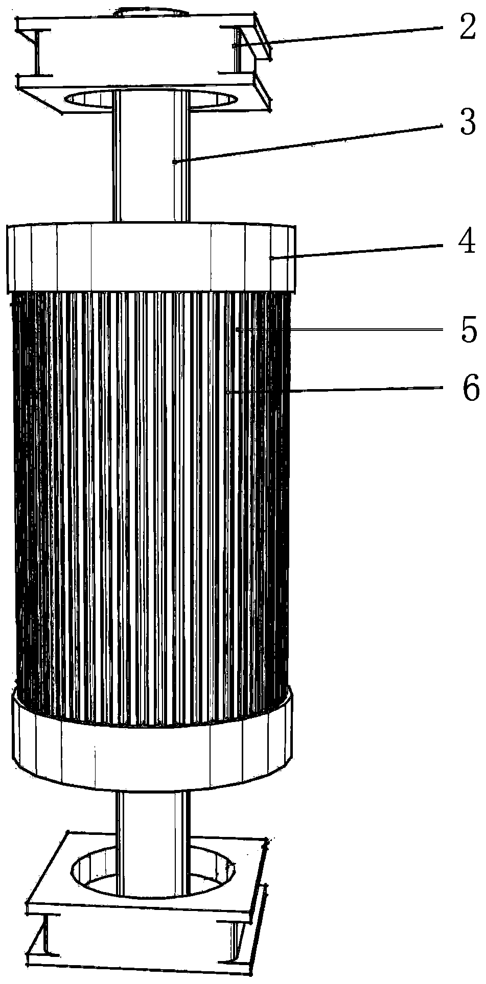
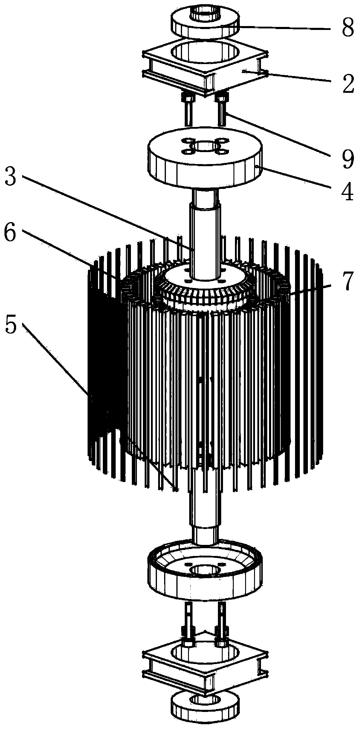
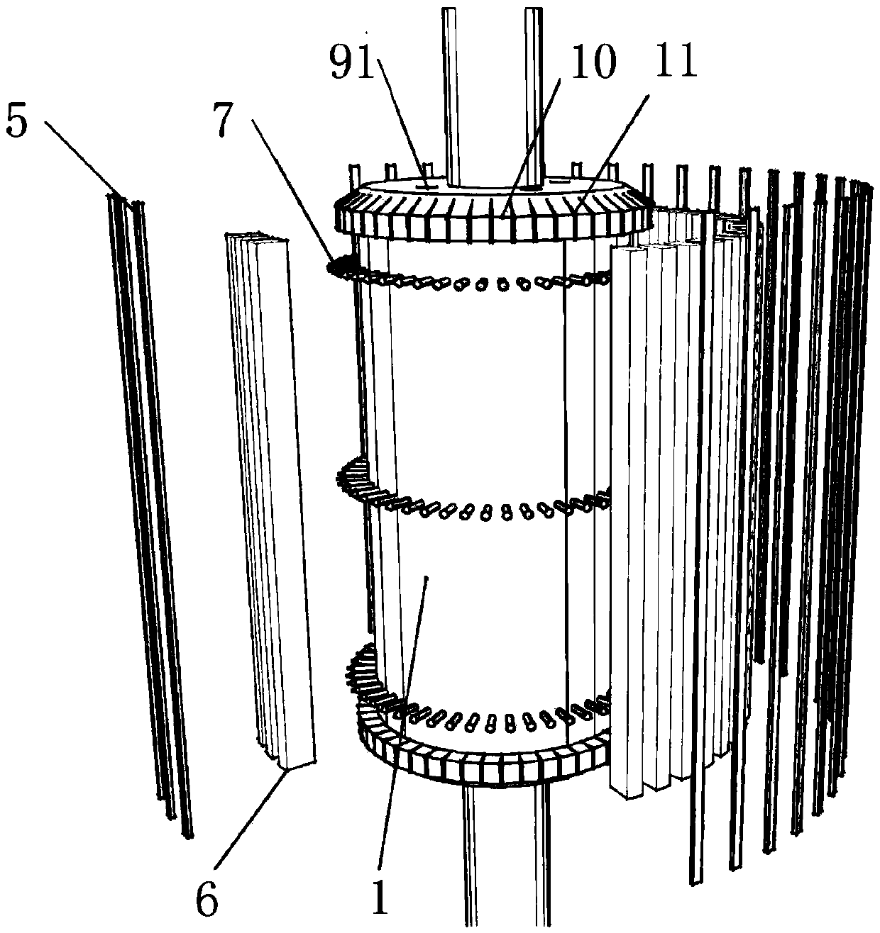
[0006] The purpose of the present invention is to provide a chopped knife holder, which can effectively solve the problem of blockage of the chopped knife holder due to the scale layer produced by the sizing agent

Method used


Image

  • A short cutting tool holder
  • A short cutting tool holder
  • A short cutting tool holder

Examples


Embodiment Construction

[0026] As mentioned in the background art section, the current chopping knife holder is easy to cause blockage of sizing agent.

[0027] Based on the above research, the embodiment of the present invention provides a chopping tool holder. By setting the blade in the rubber groove, since the rubber itself has good elasticity and sealing performance, it can make the blade and the rubber groove The side walls are tightly fitted, and the sizing produced during chopping production is difficult to enter between the blade and the rubber groove, thereby avoiding clogging. At the same time, it can ensure that the blade has sufficient elastic deformation during chopping production, and can effectively avoid failures such as gaps or breaks caused by the blade relying on its own hardness to cut yarn.

[0028] In order to make the above objects, features and advantages of the present invention more comprehensible, the specific implementation manners of the present invention will be describ...


PUM


Abstract

The invention discloses a short cutter rest which comprises a cylindrical rest body. A shaft is arranged in the middle of the cylindrical rest body; positioning grooves are uniformly distributed in the outer side wall of the rest body, the length direction of the positioning grooves is parallel to the axis of the rest body, a rubber groove is formed inside each positioning groove, and a blade is arranged inside each rubber groove. Due to the fact that the blades are arranged inside the rubber grooves, and rubber has the good elasticity and sealing performance, the blades can be tightly attached to the side walls of the rubber grooves; impregnating compound dirt produced during short cutting production cannot enter the portions between the blades and the rubber grooves easily, and therefore the phenomenon of blockage is avoided. Meanwhile, it is ensured that the blades have enough elastic deformation during short cutting production, and the phenomenon that the blades lose efficacy due to gaps or fractures caused when the blades cut yarn by means of hardness of the blades can be effectively avoided.

Description

technical field [0001] The invention relates to the technical field of glass fiber chopped production, in particular to a chopped knife holder. Background technique [0002] The knife holder used in the current glass fiber chopping process includes the main body of the knife holder with a positioning groove. When in use, the blade is inserted into the blade positioning groove in the knife holder. The blade is generally 0.3mm thick, and the positioning groove The width is about 1mm, so after the blade is installed, there is a certain gap between the blade and the side wall of the positioning groove, that is, the blade has a certain movable space in the positioning groove. [0003] However, the existing glass fiber chopping process mainly uses wet cutting. The so-called wet cutting means that the sizing agent coated on the glass fiber strands has not been dried to form a film before chopping. still wet. These wet sizing agents are highly viscous and easily adhere to the blad...

Claims


Application Information

Patent Timeline
Patent Type & Authority Patents(China)
IPC IPC(8): C03B37/16
CPCY02P40/57
Inventor 王为姚远杜洪晏斌周建刚杨丹何勇夏逐波王艺周乐云曾庆文彭珂李炜
Owner 重庆亿煊新材料科技有限公司
Learn More