
Equipment and Application for Improving Particle Distribution of In-Situ Particle Reinforced Aluminum Matrix Composites

A particle-reinforced aluminum and composite material technology, applied in the field of materials, can solve problems such as a large number of particles and agglomeration, and achieve the effects of low cost, simple equipment and simple operation

Active Publication Date: 2018-06-26
SHANGHAI JIAOTONG UNIV
View PDF4 Cites 0 Cited by
  • Summary
  • Abstract
  • Description
  • Claims
  • Application Information

AI Technical Summary

Problems solved by technology

[0005] The purpose of the present invention is to provide a device for improving the particle distribution uniformity of in-situ particle-reinforced aluminum-based composite materials and its application method in order to overcome the defects of the above-mentioned prior art, effectively breaking up the agglomerates of in-situ particles during the casting process, The process is simple and easy to operate, low cost and high efficiency, and can generate large-sized samples, which solves the technical problem of a large number of particle agglomerations in the in-situ particle reinforced aluminum matrix composite

Method used


Image

  • Equipment and Application for Improving Particle Distribution of In-Situ Particle Reinforced Aluminum Matrix Composites

Examples


Embodiment 1

[0027] In situ self-generated 5wt.%TiB obtained by casting 2 / 7050Al composite material, a large amount of TiB in the as-cast structure 2 Particles agglomerate at grain boundaries. In situ self-generated 5wt.%TiB obtained by casting 2 / 7050Al composites were homogenized at 465°C for 24 hours, and then subjected to two-pass orthogonal lamination extrusion at 450°C. Body is broken up, TiB 2 The particles are uniformly distributed in the matrix alloy. 5wt.%TiB after two passes of orthogonal extrusion 2 The / 7050Al composite was solid-soluted at 470°C for 70min and aged at 120°C for 20h, then its mechanical properties were characterized, and it had a plasticity of more than 10%, indicating that the in-situ 5wt.%TiB 2 The particle aggregates in the matrix structure of / 7050Al composites were completely broken up.

Embodiment 2

[0029] In situ self-generated 5wt.%TiB obtained by casting 2 / 2024Al composite material, there is a large amount of TiB in the as-cast structure 2 Particles agglomerate at grain boundaries. In situ self-generated 5wt.%TiB obtained by casting 2 / 2024Al composites were homogenized at 490°C for 48 hours, and then four passes of orthogonal lamination extrusion was carried out at 450°C. Body is broken up, TiB 2 The particles are evenly distributed in the matrix alloy, and 5wt.% TiB is self-generated in situ 2 The uniformity of particle distribution within the / 2024Al composite is improved.

Embodiment 3

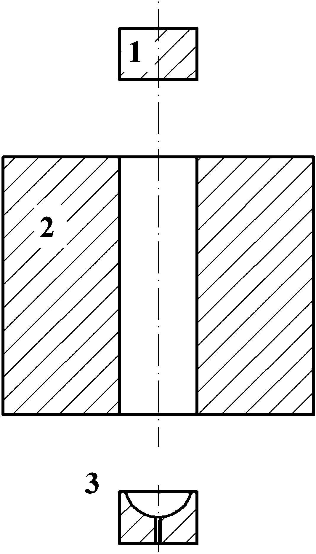
[0031] Devices for improving particle distribution of in-situ particle-reinforced aluminum matrix composites with structures such as figure 1As shown, it includes an upper pressure head 1, a mold cylinder 2 and a mold head 3. The middle part of the mold cylinder 2 is provided with a through hole with a square structure in cross section, and the side length is d. The upper pressure head 1 and the mold head 3 are connected to the through hole. When in use, the composite material is placed in the through hole, and the upper pressure head and the die head are respectively placed on the upper and lower surfaces of the composite material and pressed tightly. The die head 3 is also provided with a pit, and the bottom of the pit is provided with a through hole communicating with the bottom.

[0032] To improve the application of in-situ particle-reinforced aluminum matrix composite particle distribution equipment, the following steps are taken:

[0033] (1) The particle-reinforced al...


PUM


Abstract

The invention relates to equipment and application for improving particle distribution of in-situ particle-reinforced aluminum-based composite materials. The equipment includes an upper pressing head (1), a mold cylinder (2) and a mold head (3). The middle part of the mold cylinder (2) is provided with The through hole, the upper pressure head (1) and the die head (3) match the shape of the through hole. When using, the composite material is placed in the through hole, and the upper pressure head (1) and the die head (3) are respectively The upper and lower surfaces of the composite material and compacted. Compared with the prior art, the present invention can apply a large amount of cumulative shear to the particle-reinforced aluminum-matrix composite material by extruding the in-situ particle-reinforced aluminum-matrix composite material in this multi-pass orthogonal lamination extrusion die. Strain, and then play the role of mechanical stirring, break up the in-situ self-generated particle aggregates in the composite material, and make them evenly dispersed in the aluminum matrix, thereby improving the particle distribution uniformity of the in-situ particle-reinforced aluminum matrix composite material.

Description

technical field [0001] The invention relates to the field of materials, in particular to a device and application for improving particle distribution uniformity of in-situ particle-reinforced aluminum-based composite materials. Background technique [0002] With the development of modern science and technology, the requirements for material properties in practical applications have become more stringent. Especially in high-tech fields such as aerospace and weapon manufacturing, structural materials should have high specific stiffness and specific modulus while requiring high strength and high plasticity. However, traditional metal materials are difficult to meet such complex performance requirements. For example, although traditional steel materials have good strength and plasticity, their density is too high, so they are not suitable for a large number of applications in aerospace and other fields that have high requirements for specific strength of components; while titan...

Claims


Application Information

Patent Timeline
Patent Type & Authority Patents(China)
IPC IPC(8): C22C1/10
CPCC22C1/1036C22C1/1073
Inventor 刘钧陈哲汪明亮吴一陈东钟圣怡王浩伟
Owner SHANGHAI JIAOTONG UNIV
Learn More