A traveling car hook floating guide and elevator positioning control device for a vehicle-mounted workover rig

A floating steering and workover rig technology, applied in drilling equipment, drill pipes, casings, etc., can solve the problems of lack of rail guide devices, changes, low efficiency, etc., and achieve the effect of improving operation efficiency and reducing labor intensity

Active Publication Date: 2018-10-12
湖北省聚元石油自动化装备股份有限公司 +1
View PDF5 Cites 0 Cited by
  • Summary
  • Abstract
  • Description
  • Claims
  • Application Information

AI Technical Summary

Problems solved by technology

However, in the existing petroleum equipment, there is no device that can meet the operation requirements of the vehicle-mounted workover rig. When using the automatic derrick, the shaking of the hydraulic elevator due to strong winds, brakes, etc. The hydraulic elevator retraction during pipe string handover makes the efficiency of the handover operation very low, resulting in the use of automated derrick workers outweighing the gains.
In the operation of the vehicle-mounted workover rig, the derrick is tilted, and the angle may also change due to the operation process. In addition, in order to ensure the working space on the drilling floor and the space above the derrick and other special circumstances, the guide rail must be tilted, so floating must be adopted. guide, so there are currently no suitable rail guides available

Method used


Image

  • A traveling car hook floating guide and elevator positioning control device for a vehicle-mounted workover rig
  • A traveling car hook floating guide and elevator positioning control device for a vehicle-mounted workover rig
  • A traveling car hook floating guide and elevator positioning control device for a vehicle-mounted workover rig

Examples


Embodiment Construction

[0022] Below in conjunction with accompanying drawing, the present invention is further described as follows.

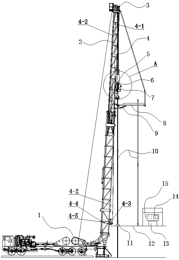
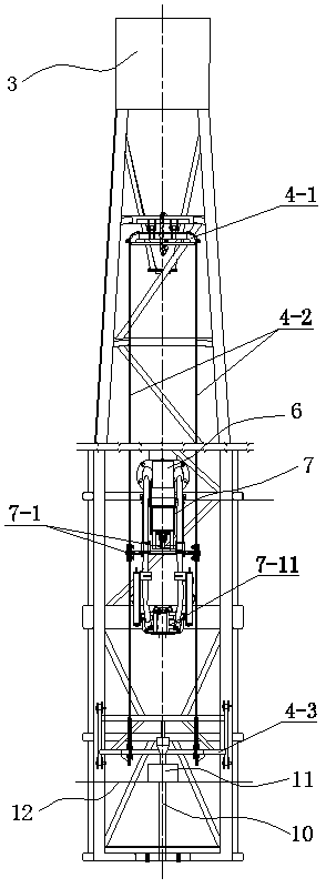
[0023] figure 1 with figure 2 Shown is a schematic diagram of a typical installation implementation case of the present invention on a vehicle-mounted workover rig.

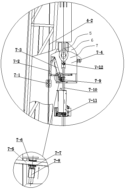
[0024]In the figure, the derrick 2 is used as the lifting and lowering support of the traveling block hook 6 of the traveling system of the workover rig, and transmits the rotation of the drawworks 1 of the workover rig to the traveling block hook 6 of the traveling system through the crown block 3; the guide rail mechanism The guide wire rope 4-2 of 4 is fixed on the upper end and the lower end of the derrick 2 through the guide wire rope upper fixing mechanism 4-1 and the guide wire rope lower fixing mechanism 4-3, providing the floating guide and the elevator positioning mechanism 7 with upstream and downstream moving guidance and alignment. Movements in other directions are constrained. In order ...


PUM


Abstract

The invention relates to a travelling block big hook floating guiding and lift sub positioning control device of a vehicle-mounted workover rig travelling system, and belongs to the technical field of vehicle-mounted workover rig matched equipment of petroleum equipment. The device consists of a guiding guide rail mechanism, a floating guiding and lift sub positioning mechanism, an electric control system and a liquid gas path control valve group, wherein the guiding guide rail mechanism is fixedly arranged on a derrick; the floating guiding and lift sub positioning mechanism is hung on a travelling block big hook, and is in floating connection with the guiding guide rail mechanism through a sliding guiding trolley; an electric control system and the liquid gas path control valve group are arranged in a driller room. Compared with a conventional travelling system, the travelling block big hook floating guiding and lift sub positioning control device has the advantages that the movement of a lift sub almost without any constraint can be thoroughly changed, so that the operation of the lift sub is stable; the position and the state are controllable; therefore the hand-over process of the hydraulic lift sub with automatic riggers, pneumatic slips, automatic catwalks and the like becomes very simple and efficient; the problems of hydraulic lift sub waggling, swinging and avoiding can be thoroughly solved; the current condition of directly pushing, pulling, opening and closing the hydraulic lift sub by operators is changed.

Description

technical field [0001] The invention relates to a traveling car hook floating guide and elevator positioning control device for a traveling system of a vehicle-mounted workover rig, and belongs to the technical field of supporting equipment for a vehicle-mounted workover rig of petroleum equipment. Background technique [0002] The traveling system of the existing vehicle-mounted workover rig is designed for manual work. The traveling system and the elevator have no track guidance. Simple gravity guidance, so that the elevator will shake and swing during the operation without load, and when the elevator needs to move horizontally or the elevator needs to be kept still due to horizontal external force, it can only be done manually Finish. When lowering a single pipe string (including sucker rod, tubing, casing, etc.), if the elevator is lowered and the coupling away from the single pipe string is too low, the single pipe string will be driven by its own weight to tilt the el...

Claims


Application Information

Patent Timeline
Patent Type & Authority Patents(China)
IPC IPC(8): E21B19/04E21B19/06
CPCE21B19/04E21B19/06
Inventor 李睿枫李金松朱海东王欣异程海蓝
Owner 湖北省聚元石油自动化装备股份有限公司
Why Eureka
Try Eureka