a dryer

A technology for dryers and drainage tanks, applied in steam boiler accessories, steam separation devices, components of steam boilers, etc., can solve the problems of reduced separation efficiency of dryers, low separation efficiency of dryers, and more water carried out, etc., to achieve Reduce production cost, avoid hydrophobic backspray, good hydrophobic effect

Active Publication Date: 2019-02-12
DONGFANG (GUANGZHOU) HEAVY MASCH CO LTD
5 Cites 0 Cited by

AI-Extracted Technical Summary

Problems solved by technology

[0003] The bottom hydrophobic plate of the dryer used in the steam generator of the existing nuclear power plant is generally a horizontal plate along the direction of steam flow, that is, the hydrophobic volume of the existing dryer hydrophobic structure is constant along the direction of steam flow. This structure cannot better match the hydrophobic flow characteristics, resulting in poor hydrophobic effect, resultin...

Method used

As a preferred embodiment, in the steam flow process, the water is gradually cooled into the water by some corrugated plates 9, and flows into the drainage box 7, because the bottom of the water drainage box 7 is inclined to set along the steam flow direction, the steam is in the flow process Because the hydrophobic flow falls below the inclined plate at the bottom of the drainage box 7, the hydrophobic volume becomes larger and larger, so that the steam is not easy to take away the dried hydrophobic again, and a better drying effect is achieved. The setting of the drainage groove and the circular conduit 6 on the upper part of the side of the drainage box 7 along the steam discharge direction can directly lead the drainage to the drainage groove through the circular conduit 6 when the amount of drainage is large, so as to achieve better performance. Drainage effect.
As a preferred embodiment, there is a drainage groove opposite to the steam outlet of the corrugated plate 9 at the side top of the drainage box 7, and the drainage groove includes the groove plate 5, which is inclined outwards at the upper side of the drainage box 7, The bottom of the drainage tank communicates with the interior of the drainage box 7, and the lower end of each circular duct 6 is below the height of the middle of the drainage box 7. When encountering a super large steam flow, the setting of the slot plate 5 is further strengthened. The ability to absorb the hydrophobicity in the steam is improved, so that the hydrophobicity in the steam treated in the dryer is further absorbed, and flows down to the bottom of the grooved plate 5 along the groove plate 5, and the bottom of the grooved plate 5 communicates...

Abstract

The invention discloses a drier. The drier comprises a drier housing and a plurality of corrugated plates which are fixed in the drier housing, wherein steam outlet and inlet are formed on the other two sides of the drier housing, respectively; a porous plate is arranged at a steam inlet end; a drain tank is fixedly arranged in the bottom of the drier housing; the bottom of the drain tank is obliquely arranged along the flowing direction of steam; a water seal device which prevents a water body from flowing reversely is arranged in the bottom of the drain tank; by means of the drain tank which is arranged obliquely along the steam direction in the bottom and the water seal device which prevents the water body from flowing reversely, a hydrophobic volume of a hydrophobic structure of the drier along the flowing direction of the steam is gradually increased and the condition that drain water is taken away again by steam is reduced, so that a better hydrophobic effect is achieved, and the water seal device which prevents the water body from flowing reversely avoids the condition that the separated drain water is ejected reversely as the inner and outer air pressures of the drier are different. The drier is simple in structure and good in hydrophobic effect, and the production cost is lowered. The drier disclosed by the invention is used for the field of steam generators.

Application Domain

Steam separation arrangementsSteam boilers +1

Technology Topic

Hydrophobic effectCistern +2

Image

  • a dryer
  • a dryer
  • a dryer

Examples

  • Experimental program(1)

Example Embodiment

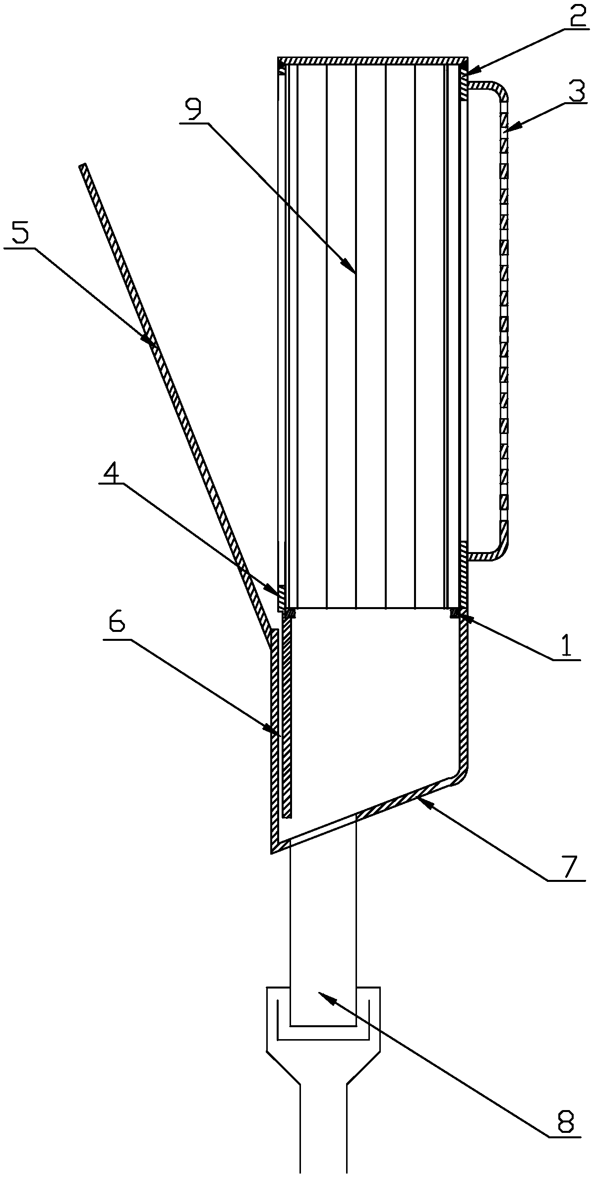
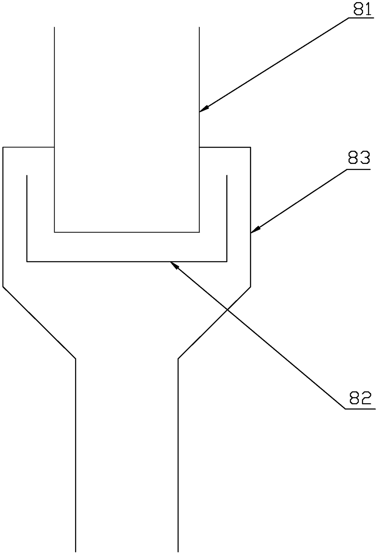
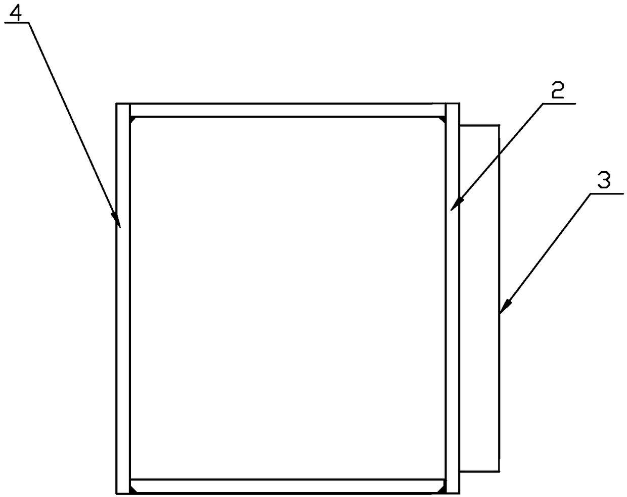
[0017] Reference Figure 1 ~ Figure 3 , The present invention is a dryer, including a dryer shell, a number of corrugated plates 9 fixed in the dryer shell, the other two sides of the dryer shell are respectively provided with steam outlet and inlet, the The steam inlet is provided with a perforated plate 3 fixedly connected to the dryer shell, and a drain box 7 is fixedly provided at the bottom of the dryer shell. The feature is that the bottom of the drain box 7 is inclined along the steam flow direction. The bottom of the drain tank 7 is provided with a water sealing device 8 to prevent backflow of the water body.
[0018] With the drainage box 7 at the bottom inclined along the steam direction and the water sealing device 8 to prevent backflow of water, the drainage volume of the dryer drainage structure along the steam flow direction is gradually increased, reducing the occurrence of the drainage being carried away by the steam again. In this way, a better hydrophobic effect is achieved, and the water sealing device 8 preventing the backflow of water prevents the separated hydrophobic from causing the hydrophobic back spray due to the different air pressure inside and outside the dryer. The dryer has a simple structure, high hydrophobic effect, and reduces production. cost.
[0019] As a preferred embodiment, on the upper side of the drain box 7, there is a drain groove opposite to the steam outlet of the corrugated plate 9. The drain groove includes a groove plate 5 that is inclined outwardly from the upper side of the drain box 7. There are several circular ducts 6 at the bottom communicating with the inside of the drain box 7. The lower end of each circular duct 6 is below the height of the middle of the drain box 7. When encountering super large steam flow, the arrangement of the groove plate 5 further enhances the steam The absorption capacity of the medium drain, so as to further absorb the drain from the steam processed in the dryer, and flow down the trough plate 5 to the bottom of the trough plate 5, and the bottom of the trough plate 5 communicates with the drain box 7, and then The absorbed drain is introduced into the drain tank 7. Because high-pressure steam also exists in the drain tank 7, the arrangement of the circular ducts 6 especially the lower end of each circular duct 6 close to the lower part of the drain tank 7 prevents The steam pressure in the drain tank 7 presses the drain back into the drain groove, which further improves the drain effect.
[0020] As a preferred embodiment, the water sealing device 8 includes a main drain pipe 81, a water seal cone 83, and a water seal groove 82 arranged in the water seal cone 83. Both ends of the main drain pipe 81 are connected to the drain box 7 and the water seal cone respectively. 83 is connected and the water sealing device 8 is set. When the outside air pressure is higher than the air pressure in the main drain pipe 81 during the drain discharge to the outside space, it prevents the drain from being pushed back to the drain tank 7 by the outside air pressure. , Thereby improving the hydrophobic effect, but also improving the safety of the equipment.
[0021] As a preferred embodiment, the two upper and lower connecting ends of the perforated plate 3 are respectively bent toward the inside of the dryer housing, and the upper bent end of the perforated plate 3 is fixedly connected to the upper end of the dryer housing through the front sealing plate 2. The lower bent end is fixedly connected to the drain box 7, and the two upper and lower connecting ends of the perforated plate 3 are bent and arranged, which also improves the working space of the dryer to a certain extent.
[0022] As a preferred embodiment, the lower end of the corrugated plate 9 at the outlet of the dryer and the drain box 7 are fixedly connected by the rear sealing plate 4, and the lower ends of the other corrugated plates 9 are respectively fixedly connected by the corresponding fixed bottom plate 1, and the two fixed bottom plates 1 The ends are respectively fixedly connected with the side plates of the dryer.
[0023] As a preferred embodiment, in the process of steam flow, the drain is gradually cooled by several corrugated plates 9 into a drain, and flows into the drain box 7. Because the bottom of the drain box 7 is arranged obliquely along the steam flow direction, the steam is drained during the flow process. Flowing down to the bottom of the inclined plate at the bottom of the drain box 7 causes the drainage volume to become larger and larger, and the steam is not easy to take away the dried drainage again, achieving a better drying effect. The arrangement of the drainage groove and the circular duct 6 opened on the upper side of the drainage box 7 along the steam discharge direction can directly lead the drainage into the drainage groove through the circular duct 6 when the drainage amount is large, so as to achieve better Drainage effect.
[0024] Of course, the invention is not limited to the above-mentioned embodiments. Those skilled in the art can make equivalent modifications or substitutions without departing from the spirit of the invention. These equivalent modifications or substitutions are all included in the claims of this application. Within the limited range.

PUM

no PUM

Description & Claims & Application Information

We can also present the details of the Description, Claims and Application information to help users get a comprehensive understanding of the technical details of the patent, such as background art, summary of invention, brief description of drawings, description of embodiments, and other original content. On the other hand, users can also determine the specific scope of protection of the technology through the list of claims; as well as understand the changes in the life cycle of the technology with the presentation of the patent timeline. Login to view more.

Similar technology patents

Hydrophobic waterproof emulsion and preparation method thereof

PendingCN114318939AThe ratio is scientific and reasonableGood hydrophobic effect
Owner:佛山市桥通新材料有限公司

Forming method of bionic porous structure with hydrophobic resistance reducing capability

PendingCN113846365AStrong lodging resistanceGood hydrophobic effect
Owner:725TH RES INST OF CHINA SHIPBUILDING INDAL CORP

Multi-composite modified hydrophobic stone-like coating and preparation method thereof

PendingCN111847989AGood water resistanceGood hydrophobic effect
Owner:广东福莱特建筑材料有限公司

Production method of cooling machine inner cylinder coating

InactiveCN109181380AGood hydrophobic effecteasy to manufacture
Owner:四川省荣律科技有限公司

Classification and recommendation of technical efficacy words

  • Good hydrophobic effect
  • prevent backflow of water

Preparation method of super-hydrophobic non-iridescence structural color film

InactiveCN110449329AHigh color saturationGood hydrophobic effect
Owner:JILIN UNIV

Transparent sound-absorption film surface hydrophobic self-cleaning coating and preparation method thereof

InactiveCN103275571AGood light transmittanceGood hydrophobic effect
Owner:NANJING UNIV OF SCI & TECH

Dry seamless undergarment and production process thereof

InactiveCN102763904AGood hydrophobic effect
Owner:HAINING YILITE KNITTING

Water-soluble system structure based on isocyanate-yl alkyl alkoxy silane and preparation method thereof

InactiveCN101712747AGood water solubilityGood hydrophobic effect
Owner:武汉壁千韧硅涂料有限公司

Anti-graffiti and scrubbing-resistant coating composition and preparation method thereof

ActiveCN113122091ALow VOCGood hydrophobic effect
Owner:HEBEI CARPOLY PAINT CO LTD +1

Efficient concrete additive raw material drying device

InactiveCN112595028Aprevent backflow of wateravoid clogging
Owner:江苏中鼎建材集团有限公司
Why Eureka
Try Eureka